Mathematical Instruments
Book IV. Additions. Ch. II.

Of the Construction and Use of the Plain-Table, and Circumferentor.

Fig. F

The Table itself is a Parallelogram of Oak, or other Wood, about 15 Inches long, and 12 broad, consisting of two several Boards, round which are Ledges of the same Wood; the two opposite of which being taken off, and the Spangle unskrewed from the Bottom, the aforesaid two Boards may be taken asunder for ease and conveniency of Carriage. For the binding of the two Boards and Ledges fast, when the Table is set together, there is a Box Jointed-Frame, about \(\frac{3}{4}\) of an Inch broad, and of the same thickness as the Boards, which may be folded together in 6 Pieces. This Frame is so contrived, that it may be taken off and put on the Table at pleasure, and may go easily on the Table, either side being upwards. This Frame also is to fasten a Sheet of Paper upon the Table, by forcing down the Frame, and squeezing in all the Edges of the Paper; so that it lies firm and even upon the Table, that thereby the Plot of a Field, or other Inclosure, may conveniently be drawn upon it.

On both sides this Frame, near the inward Edge, are Scales of Inches subdivided into 10 equal Parts, having their proper Figures set to them. The Uses of these Scales of Inches, are for ready drawing of Parallel Lines upon the Paper; and also for shifting your Paper, when one Sheet will not hold the whole Work.

Upon one side of the said Box Frame, are projected the 360 Degrees of a Circle from a Brass Center-Hole in the Middle of the Table. Each of these Degrees are subdivided into 30 Minutes; to every 10th Degree is set two Numbers, one expressing the proper Number of Degrees, and the other the Complement of that Number of Degrees to 360. This is done to avoid the trouble of Substraction in taking of Angles.

On the other Side of this Frame, are projected the 180 Degrees of a Semi-Circle from a Brass Center-Hole, in the Middle of the Table’s length, and about a fourth Part of it’s breadth. Each of these Degrees are subdivided into 30 Minutes; to every 10th Degree is set likewise, as on the other side, two Numbers; one expressing the proper Number of Degrees, and the other the Complement of that Number of Degrees to 180, for the same Reason, as before.

The manner of projecting the Degrees on the aforesaid Frame, is, by having a large Circle divided into Degrees, and every 30 Minutes: For then placing either of the Brass Center-Holes on the Table, in the Center of that Circle so divided, and laying a Ruler from that Center to the Degrees on the Limb of the Circle; where the Edge of the Ruler cuts the Frame, make Marks for the Correspondent Degrees on the Frame.

The Degrees thus intersect on the Frame, are of excellent use in wet or stormy Weather, when you cannot keep a Sheet of Paper upon the Table. Also these Degrees will make the Plain-Table a Theodolite, or a Semi-Circle, according as what side of the Frame is upper-most.

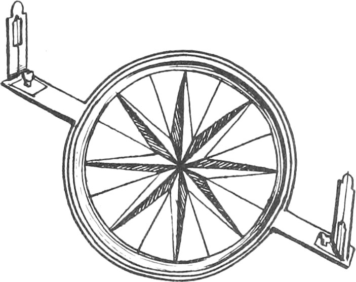
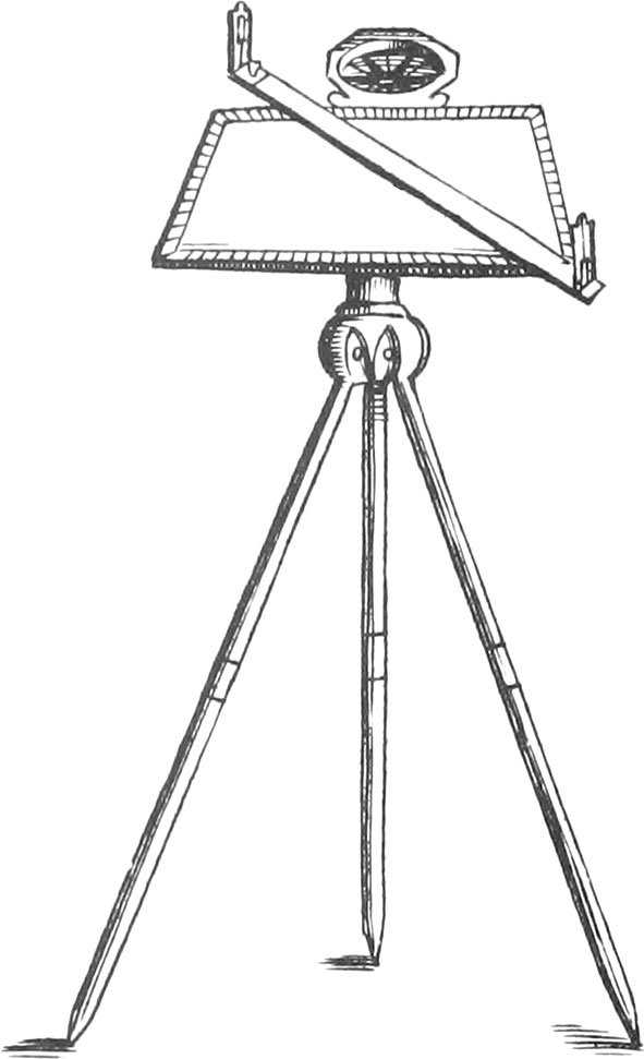
There is a Box, with a Needle and Card, covered with a Glass, fixed to one of the long Sides of the Table, by means of a Screw, that thereby it may be taken off. This Box and Needle is very useful for placing the Instrument in the same Position upon every remove.

There belongs to this Instrument a Brass Socket and Spangle, screwed with three Screws to the Bottom of the Table, into which must be put the Head of the three-legged Staff, which may be screwed fast, by means of a Screw in the Side of the Socket.

There is also an Index belonging to the Table, which is a large Brass Ruler, at least 16 Inches long, and 2 Inches broad, and so thick as to make it strong and firm, having a sloped Edge, called the Fiducial Edge, and two Sights screwed perpendicularly on it, of the same Height. They must be set on the Ruler perfectly at the same Distance from the Fiducial Edge. Upon this Index it is usual to have many Scales of equal Parts, as also Diagonals, and Lines of Chords.

Section I. Of the Construction of the Circumferentor.

Fig. G

This Instrument consist of a Brass Index and Circle, all of a Piece; the Index is commonly made about 14 Inches long, an Inch and half broad, and of a convenient Thickness. The Diameter of the aforenamed Circle is about 7 Inches. On this Circle is made a Card, whose Meridian Line answers to the Middle of the Breadth of the Index: That Card is divided into 360 Degrees. There is a Brass Ring soldered on the Circumference of the Circle, on which screws another Ring with a flat Glass in it; so that they make a kind of Box to contain the Needle suspended upon the Pivot placed in the Center of the Circle.

There are also two Sights to screw on, or slide up and down the Index, like those before-named, belonging to the Index of the Plain-Table; as likewise a Spangle and Socket screwed on to the back-side of the Circle, for putting the Head of the Staff in.

Section II. Of the Use of he Plain-Table and Circumferentor.

But first, it is necessary to know how to set the Parts of the Plain-Table together, to make it fit for use.

When you would make your Table fit for use, lay the two Boards together, and also the Ledges at the Ends in their due Places, according as they are marked. Then lay a Sheet of white Paper all over the Table, which must be stretched over the Boards, by putting on the Box Frame, which binds both the Paper to the Boards, and the Boards to one another: Then screw the Socket on the back-side the Table, and also the Box and Needle in it’s due Place, the Meridian Line of the Card lying parallel to the Meridian or Diameter of the Table; which Diameter is a Right Line drawn upon the Table, from the Beginning of the Degrees thro’ the Center, and so to the End of the Degrees. Then put the Socket upon the Head of the Staff, and there screw it: Also put the Sights upon the Index, and lay the Index on the Table. So is your Instrument prepared for use, as a Plain-Table, Theodolite, or Semi-Circle.

But Note, It is either a Theodolite, or Semi-Circle, according as the Theodolite or Semi-Circular Side of the Frame is upwards; for when you use your Instrument as a Plain-Table, you may place your Center in any part of the Table, which you judge most proper for bringing on the Work you intend. But if you use your Instrument as a Theodolite, the Index must be turned about upon the Brass Center-Hole in the Middle of the Table; and if for a Semi-Circle, upon the other Brass Center-Hole, by means of a Pin or Needle placed therein.

If you have a mind to use this Instrument, as a Circumferentor, you need only screw the Box and Needle to the Index, and both of them to the Head of the Staff, with a Brass Screw-Pin fitted for that purpose: So that the Staff being fixed in any Place, the Index and Sights, may turn about at pleasure, without moving the Staff.

Use I. How to measure the Quantity of any Angle in the Field, by the Plain-Table, considered as a Theodolite, Semi-Circle, and Circumferentor.

Fig. 1

I. How to observe an Angle in the Field by the Plain-Table.

Suppose EK, KG, to be two Hedges, or two Sides of a Field, including the Angle EKG, and it is required to draw upon the Table an Angle equal thereto: First place your Instrument as near the Angular Point K as conveniency will permit, turning it about, ’till the North End of the Needle hangs directly over the Meridian Line in the Card, and then screw the Table fast. Then upon your Table, with your Protracting-Pin (which is a fine Needle put into a Piece of Box or Ivory, neatly turned) or Compass-Point, assign any Point at pleasure upon the Table, and to that Point apply the Edge of the Index, turning the Index about upon that Point, ’till thro’ the Sights thereof you see a Mark set up at E, or parallel to the Line EK: And then with your Protracting-Pin, Compass-Point, or Pencil, draw a Line by the Side of the Index to the assigned Point upon the Table. Then (the Table remaining immoveable) turn the Index about upon the forementioned Point, and direct the Sights to the Mark set up at G, or parallel thereto, that is, so far distant from G, as your Instrument is placed from K; and then by the Side of the Index draw another Line to the assigned Point. Thus will there be drawn upon the Table two Lines representing the Hedges EK, and KG; and which include an Angle equal to the Angle EKG. And tho’ you know not the Quantity of this Angle, yet you may find it, if required: For in working by this Instrument, it is sufficient only to give the Proportions of Angles, and not their Quantities in Degrees, as in working by the Theodolite, Semi-Circle, or Circumferentor. Also in working by the Plain-Table, there needs no Protraction at all, for you will have upon your Table the true Figure of any Angle or Angles that you observe in the Field, in their true Position, without any further trouble.

II. How to find the Quantity of an Angle in the Field, by the Plain-Table, considered as a Theodolite, or Semi-Circle.

Let it first be required to find the Quantity of the Angle EKG by the Plain-Table, as a Theodolite: Place your Instrument at K, with the Theodolite side of the Frame upwards, laying the Index upon the Diameter thereof, then turn the whole Instrument about (the Index still resting upon the Diameter) ’till thro’ the Sights you espy the Mark at E: Then screwing the Instrument fast there, turn the Index about upon the Theodolite Center-Hole in the Middle of the Table, ’till thro’ the Sights you espy the Mark at G. Then note what Degrees on the Frame of the Table are cut by the Index, and those will be the Quantity of the Angle EKG sought.

You must proceed in the same manner for finding the Quantity of an Angle by the Plain-Table as a Semi-Circle; only put the Semi-Circle side of the Frame upwards, and move the Index upon the other Center-Hole.

III. How to observe the Quantity of an Angle by the Circumferentor.

If it be required to find the Quantity of the former Angle EKG by the Circumferentor, First, place your Instrument (as before) at K, with the Flower-de-luce in the Card towards you. Then direct your Sights to E, and observe what Degrees are cut by the South-End of the Needle, which let be 296; then turning the Instrument about (the Flower-de-luce always towards you), direct the Sights to G, noting then also, what Degrees are cut by the South-End of the Needle, which suppose 182. This done (always) substract the lesser from the greater, as in this Example 182 from 296, and the Remainder is 114 Degrees; which is the true Quantity of the Angle EKG.

Again; The Instrument standing at K, and the Sights being directed to E, as before, suppose the South-End of the Needle had cut 79 Degrees; and then directing the Sights to G, the same End of the Needle had cut 325 Degrees. Now, if from 325 you substract 79, the Remainder is 246. But because this Remainder 246 is greater than 180, you must therefore substract 246 from 360, and there will remain 114, the true Quantity of the Angle sought.

This adding and substracting for finding of Angles may seem tedious to some. But here note, That for quick dispatch the Circumferentor is as good an Instrument as any, for in going round a Field, or in surveying a whole Manor, you are not to take notice of the Quantity of any Angle; but only to observe what Degrees the Needle cuts: as hereafter will be manifest.

Use II. How by the Plain-Table, to take the Plot of a Field at one Station within the same, from whence all the Angles of the same Field may be seen.

Fig. 2

Having entered upon the Field to survey, your first work must be to set up some visible Mark at each Angle thereof; which being done, make choice of some convenient Place about the Middle of the Field, from whence all the Marks may be seen, and there place your Table covered with a Sheet of Paper, with the Needle hanging directly over the Meridian Line of the Card (which you must always have regard to, especially when you are to survey many Fields together). Then make a Mark about the Middle of the Paper, to represent that part of the Field where the Table stands; and laying the Index upon this Point, direct your Sights to the several Angles where you before placed Marks, and draw Lines by the Side of the Index upon the Paper. Then measure the Distance of every of these Marks from your Table, and by your Scale set the same Distances upon the Lines drawn upon the Table, making small Marks with your Protracting-Pin, or Compass-Point, at the End of every of them. Then Lines being drawn from the one to the other of these Points, will give you the exact Plot of the Field; all the Lines and Angles upon the Table being proportional to those of the Field.

Example; Suppose the Plot of the Field ABCDEF was to be taken. Having placed Marks in the several Angles thereof, make choice of some proper Place about the Middle of the Field, as at L, from whence you may behold all the Marks before placed in the several Angles; and there place your Table. Then turn your Instrument about, ’till the Needle hangs over the Meridian Line of the Card, denoted by the Line NS.

Your Table being thus placed with a Sheet of Paper thereon, make a Mark about the Middle of your Table, which shall represent the Place where your Table stands. Then, applying your Index to this Point, direct the Sights to the first Mark at A, and the Index setting there, draw a Lire by the Side thereof to the Point L. Then with your Chain measure the Distance from L, the Place where your Table stands, to A, the first Mark, which suppose 8 Chains, 10 Links. Then take 8 Chains 10 Links from any Scale, and let that Distance upon the Line from L to A.

Then directing the Sights to B, draw a Line by the Side of the Index, as before, and measure the Distance from your Table at L, to the Mark at B, which suppose 8 Chains 75 Links. This distance taken from your Scale, and applied to your Table from L to B, will give the Point B, representing the second Mark.

Then direct the Sights to the third Mark C, and draw a Line by the Side of the Index, measuring the Distance from L to C, which suppose 10 Chains 65 Links. This Distance being taken from your Scale, and applied to your Table from L to C, will give you the Point C, representing the third Mark.

In this manner you must: deal with the rest of the Marks at D, E, and F, and more, if the Field had consisted of more Sides and Angles.

Lastly; When you have made Observations of all the Marks round the Field, and found the Points ABCDE and F upon your Table, you must draw Lines from one Point to another, ’till you conclude where you first begun. As, draw a Line from A to B, from B to C, from C to D, from D to E, from E to F, and from F to A, where you begun; then will ABCDEF, be the exact Figure of your Field, and the Line NS the Meridian.

Note, Our Chains are commonly 4 Poles in Length, and are divided into one hundred equal Parts, called Links, at every tenth of which are Brass Distinctions numbering them.

Use III. To take the Plot of a Wood, Park, or other large Champain Plain, by the Plain-Table, in measuring round about the same.

Fig. 3

Suppose ABCDEFG to be a large Wood, whose Plot you desire to take upon the Plain-Table.

  1. Having put a Sheet of Paper upon the Table, place your Instrument at the Angle A, and direct your Sights to the next Angle at B, and by the Side thereof draw a Line upon your Table, as the Line AB. Then measure by the Hedge-Side from the Angle A to the Angle B, which suppose 12 Chains 5 Links. Then from your Scale take 12 Chains 5 Links, and lay off upon your Table from A to B. Then turn the Index about, and direct the Sights to G, and draw the Line AG upon the Table. But at present you need not measure the Distance.
  2. Remove your Instrument from A, and set up a Mark where it last stood, and place your Instrument at the second Angle B. Then laying the Index upon the Line AB, turn the whole Instrument about, ’till thro’ the Sights you see the Mark set up at A, and there screw the Instrument. Then laying the Index upon the Point B, direct your Sights to the Angle C, and draw the Line BC upon your Table. Then measuring the Distance BC 4 Chains 45 Links, take that Distance from your Scale, and set it upon your Table from B to C.
  3. Remove your Instrument from B, and set up a Mark in the room of it, and place your Instrument at C, laying the Index upon the Line CB; and turn the whole Instrument about, ’till thro’ the Sights you espy the Mark set up at B, and there fasten the Instrument. Then laying the Index on the Point C, direct the Sights to D, and draw upon the Table the Line CD. Then measure from C to D 8 Chains 85 Links, and set that Distance upon your Table from C to D.
  4. Remove the Instrument to D (placing a Mark at C, where it last stood), and lay the Index upon the Line DC, turning the whole Instrument about, ’till thro’ the Sights you see the Mark at C, and there fasten the Instrument. Then lay the Index on the Point D, and direct the Sights to E, and draw the Line DE. Then with your Chain measure the Distance DE 13 Chains 4 Links, which lay off on the Table from D to E.
  5. Remove your Instrument to E (placing a Mark at D, where it last stood), and laying the Index upon the Line DE, turn the whole Instrument about, ’till thro’ the Sights you see the Mark at D, and there fasten the Instrument. Then lay the Index on the Point E, and direct the Sights to F, and draw the Line EF. Then measure the Distance EF 7 Chains 70 Links, which take from your Scale, and lay off from E to F.
  6. Remove your Instrument to F, placing a Mark at E (where it last stood), and lay the Index upon the Line EF, turning the Instrument about, ’till you see the Mark set up at E, and there fasten the Instrument. Then laying the Index on the Point F, direct the Sights to G, and draw the Line FG upon the Table, which Line FG will cut the Line AG in the Point G. Then measure the Distance FG 5 Chains 67 Links, and lay it off from F to G.
  7. Remove your Instrument to G (setting a Mark where it last stood), and lay the Index upon the Line FG, turning the whole Instrument about, ’till thro’ the Sights you see the Mark at F, and there fasten the Instrument. Then laying the Index upon the Point G, direct the Sights to A (your first Mark), and draw the Line GA, which, if you have truly wrought, will pass directly thro’ the Point A, where you first began.

In this manner may you take the Plot of any Champain Plain, be it never so large. And here note, That very often Hedges are of such a Thickness, that you cannot come near the Sides or Angles of the Field, either to place your Instrument, or measure the Lines. Therefore in such Cases you must place your Instrument, and measure your Lines parallel to the Side thereof; and then your Work will be the same as if you measured the Hedge itself.

Note also, That in thus going about a Field, you may much help yourself by the Needle. For looking what Degree of the Card the Needle cuts at one Station, if you remove your Instrument to the next Station, and with your Sights look to the Mark where the Instrument last stood, you will find the Needle to cut the same Degree again, which will give you no small Satisfaction in the prosecution of your Work. And tho’ there be a hundred or more Sides, the Needle will still cut the same Degree at all of them, except you have committed some former Error: therefore at every Station have an Eye to the Needle.

Fig. 4
Fig. 5

Of Shifting of Paper.

In taking the Plot of a Field by the Plain-Table, and going about the same, as before directed, it may so fall out, if the Field be very large, and when you are to take many Inclosures together, that the Sheet of Paper upon the Table will not hold all the Work. But you must be forced to take off that Sheet, and put another clean Sheet in the room thereof: and, in Plotting of a Manor or Lordship, many Sheets may be thus changed, which we call Shifting of Paper. The Manner of performing thereof is as follows.

Suppose in going about to take the Plot ABCDEFG, as before directed, that you having made choice of the Angle at A for the Place of the Beginning, and proceeded from thence to B, and from B to C, and from C to D, when you come to the Angle at D, and are to draw DE, you want room to draw the same upon the Table. Do thus:

First, thro’ the Point D draw the Line DO, which is almost so much of the Line DE, as the Table will contain. Then near the Edge of the Table HM, draw a Line parallel to HM, by means of the Inches and Subdivisions on the opposite Sides of the Frame, as PQ, and another Line at Right Angles to that thro’ the Point O, as ON. This being done, mark this Sheet of Paper with the Figure (1) about the Middle thereof, for the first Sheet. Then taking this Sheet off your Table, put another clean Sheet thereon, and draw upon it a Line parallel to the contrary Edge of the Table, as the Line RS. Then taking your first Sheet of Paper, lay it upon the Table so, that the Line PQ may exactly lie upon the Line RS, to the best advantage, as at the Point O (Fig. 5.). Then with the Point of your Compasses draw so much of the Line OD upon the clean Sheet of Paper as the Table will hold. Having thus done, proceed with your Work upon the new Sheet, beginning at the Point O; and so going forward with your Work, as in all Respects has before been directed; as from O to E, from E to F, from F to G, and from G to A (by this direction), shifting your Paper as often as you have occasion.

Use IV. How to take the Plot of any Wood, Park, &c. by going about the same, and making Observations at every Angle thereof, by the Circumferentor.

Fig. 6

Suppose ABCDEFGHK is a large Field, or other Inclosure, to be Plotted by the Circumferentor.

  1. Placing your Instrument at A (the Flower-de-luce being towards you), direct the Sights to B, the South-End of the Needle cutting 191 Degrees, and the Ditch, Wall, or Hedge, containing 10 Chains 75 Links. The Degrees cut, and the Line measured, must be noted down in your Field-Book.
  2. Place your Instrument at B, and direct the Sights to C, the South-End of the Needle cutting 279 Degrees, and the Line BC containing 6 Chains 83 Links; which note down in your Field-Book.
  3. Place the Instrument at C, and direct the Sights to D, the Needle cutting 216 Deg. 30 Min. and the Line CD containing 7 Chains 82 Links.
  4. Place the Instrument at D, and direct the Sights to E, the Needle cutting 327 Degrees, and the Line DE containing 9 Chains 96 Links.
  5. Place the Instrument at E, and direct the Sights to F, the Needle cutting 12 Deg. 30 Min. and the Line FE 9 Chains 71 Links.
  6. Place the Instrument at F, and direct the Sights to G, the Needle cutting 342 Deg. 30 Min. and the Line FG being 7 Chains 54 Links.
  7. Place the Instrument at G, and direct the Sights to H, the Needle cutting 98 Deg. 30 Min. and the Line GH containing 7 Chains 52 Links.
  8. Place the Instrument at H, and direct the Sights to K, the Needle cutting 71 Deg. and the Line HK containing 7 Chains 78 Links.
  9. Place the Instrument at K, and direct the Sights to A (where you began), the Needle cutting 161 Deg. 30 Min. and the Line KA containing 8 Chains 22 Links.

Having gone round the Field in this manner, and collected the Degrees cut, and the Lines measured, in the Field-Book, you will find them to stand as follows, by which you may protract and draw your Field, as presently I shall shew.

Degrees Minutes Chains Links
A191001075
B27900683
C21630782
D32500696
E1230971
F32430754
G9830754
H7100778
K16130822

In going about a Field in this manner, you may perceive a wonderful quick Dispatch; for you are only to take notice of the Degrees cut once at every Angle, and not to use any Back-Sights, that is, to look thro’ the Sights to the Station you last went from. But to use Back-Sights with the Circumferentor, is best to confirm your Work: For when you stand at any Angle of a Field, and direct your Sights to the next, and observe what Degrees the South-End of the Needle cuts; if you remove your Instrument from this Angle to the next, and look to the Mark or Angle where it last stood, the Needle will there also cut the same Degrees as before.

So the Instrument being placed at A, if you direct the Sights to B, you will find the Needle to cut 191 Degrees; then removing your Instrument to B, if you direct the Sights to A, the Needle will then also cut 191 Degrees.

Notwithstanding the quick Dispatch this Instrument makes, one half of the Work will almost be saved; if, instead of placing the Instrument at every Angle, you place it but at every other Angle. An Instance of which take in the aforegoing Example.

  1. Placing the Instrument at A, and directing the Sights to B, you find the Needle to cut 191 Degrees. Then,
  2. Placing the Instrument at B, directing the Sights to C, you find the Needle to cut 279 Degrees. And,
  3. Placing the Instrument at C, and directing the Sights to D, you find the Needle to cut 216 Degrees.

Now, having placed your Instrument at A, and noted down the Degrees cut by the Needle, which was 191, you need not go to the Angle B at all, but go next to the Angle C, and there place your Instrument; and directing your Sights backwards to B, you will find the Needle to cut 279 Degrees, which are the same as were before cut when the Instrument was placed at B: so that the Labour of placing the Instrument at B is wholly saved. Then (the Instrument still standing at C) direct the Sights to D, and the Needle will cut 216 Degrees, as before, which note in your Field-Book. This done, remove your Instrument to E, and observe according to the last Directions, and you will find the Work to be the same as before. Then remove the Instrument from E to G, from G to K, and so to every second Angle.

Fig. 7

I now proceed, to shew the Manner of Protracting the former Observations.

According to the largeness of your Plot provide a Sheet of Paper, as LMNO, upon which draw the Line LM, and parallel thereto draw divers other Lines quite thro’ the whole Paper, as the pricked Lines, in the Figure, drawn between LM and NO. These Parallels thus drawn, represent Meridians. Upon one or other of these Lines, or parallel to one of them, must the Diameter of your Protractor be always laid.

  1. Your Paper being thus prepared, assign any Point upon any of the Meridians, as A, upon which place the Center of the Protractor, laying the Diameter thereof upon the Meridian Line drawn upon the Paper. Then look in your Field-Book what Degrees the Needle cuts at A, which was 191 Degrees. Now, because the Degrees were above 180, you must therefore lay the Semi-Circle of the Protractor downwards, and keeping it there, make a Mark with the Protracting-Pin against 191 Degrees; thro’ which Point, from A, draw the Line AB, containing 10 Chains 75 Links.
  2. Lay the Center of the Protractor on the Point B, with the Diameter in the same Portion as before directed (which always observe). And because the Degrees cut at B were more than 180, viz. 279, therefore the Semi-Circle of the Protractor must lie downwards; and so holding it, make a Mark against the 279 Degrees, and thro’ it draw the Line BC, containing 6 Chains 83 Links.
  3. Place the Center of the Protractor on the Point C. Then the Degrees cut by the Needle at the Observation in C, being above 180, namely, 216 Degrees 30 Minutes, the Semi-Circle of the Protractor must lie downwards. Then making a Mark against 216 Deg. 30 Min. thro’ it draw the Line CD, containing 7 Chains 82 Links.
  4. Lay the Center of the Protractor upon the Point D; the Degrees cut by the Needle at that Angle being 325: which being above 180, lay the Semi-Circle downward; and against 325 Degrees make a Mark, thro’ which Point, and the Angle D, draw the Line DE, containing 6 Chains 96 Links.
  5. Remove your Protractor to E. And because the Degrees cut by the Needle at this Angle were less than 180, namely, 12 Degrees 30 Min. therefore lay the Semi-Circle of the Protractor upwards, and make a Mark, against 12 Degrees 30 Minutes, thro’ which draw the Line EF, containing 9 Chains 71 Links.
  6. Lay the Center of the Protractor upon the Point F; and because the Degrees to be protracted are above 180, viz. 342 Degrees 30 Minutes, lay the Semi-Circle of the Protractor downwards, and make a Mark against: 342 Degrees 30 Minutes, drawing the Line FG, containing 7 Chains 54 Links.

And in this Manner must you protract all the other Angles, G, H, and K, and more, if the Field had consisted of more Angles.

  1. Previous Book IV Additions. Chapter I. Theodolite
  2. Contents
  3. Next Book IV Additions. Chapter III. Surveying-Wheel