Mathematical Instruments
Suppl. Ch. IV.

Some Account of the great Mural Quadrant at the Royal Observatory in Greenwich Park.

Fig. 9

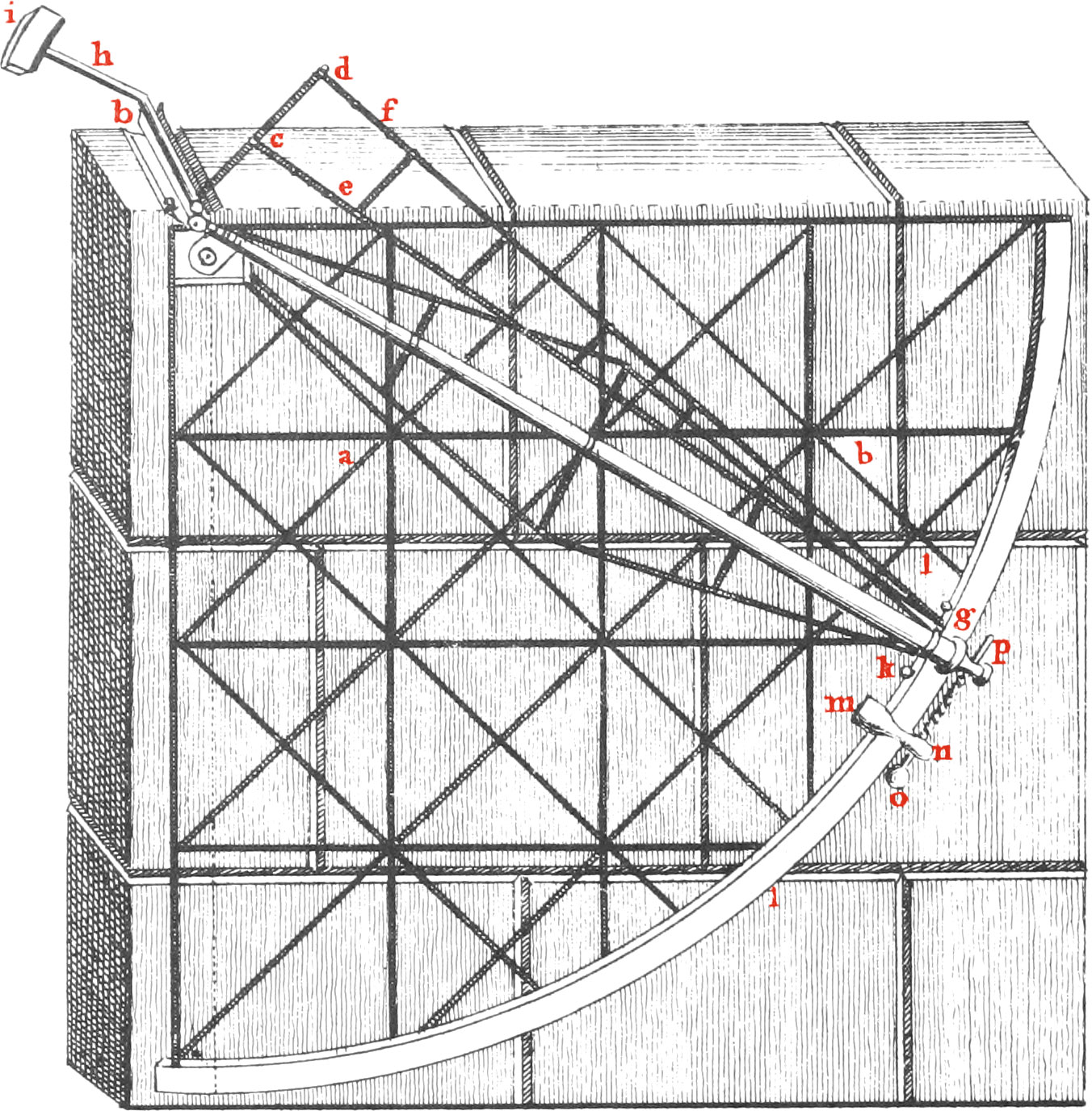
Quadrant chiefly consists of streight Iron Bars, cross-ways joined together (as appears in the Figure) flat-ways and edge-ways, the Breadth of each of which is 2 Inches and 9 Tenths, and the Thickness \(\frac{1}{10}\) and \(\frac{3}{4}\) nearly; all those that are edge-ways being behind the others. They are so placed to strengthen them the more, and are besides farther strengthened by a great Number of short Iron Plates bent to a right Angle, and placed behind the Quadrant in the Angles made by the Bars, and riveted to them both. Behind at the Circumference of the Quadrant there is also a Bar placed edge-ways, bent circular, and fastened all along the middle of the flat Arch or Limb of the Quadrant, by a sufficient Number of little Iron Plates bent at right Angles.

The Arch or Limb of the Quadrant consists of two (every ways) equal quadrantal Arches laid upon one another; an Iron one behind, and a Brass one before; the Breadth of each being 3 Inches and 4. Tenths; and the common Part of their Breadths where they lie doubled one over the other and are riveted together, is 2 Inches and 2 Tenths; the Brass Limb being remoter from the Center, than the Iron one by 1 Inch and 2 Tenths. This Limb is reduced to a true Plane, by first placing the flat of the Quadrant very firm upon a Level or Horizontal Plane, and erecting perpendicularly over it’s Center an Iron Axis, to the Bottom of which Axis is fixed at right Angles, an Iron Arm, equal in Length to the Radius of the Quadrant, and to the other End of this Arm is fixed an Iron Scraper directly over the Brass Limb, and being firmly supported by the Arm and it’s Braces, was turned about the aforesaid Axis, ’till by scraping the Brass, the Surface of it was reduced to a perfect Plane; the Edge of the Scraper being exactly perpendicular to the Axis of it’s Motion.

Upon the Brass Limb, there are two Arches struck, one with a Radius of 96.85 Inches and the other with a Radius of 95.8 Inches, by a Beam-Compass, secured from bending by several Braces fastened to it; the inner Arch is divided into Degrees, and 12th Parts of a Degree; and the outward Arch into 96 equal Parts, each of which are subdivided into 16 equal Parts. These Divisions were made by bisecting every one of the equal Arches of 30 Degrees of the Quadrant, whereby the same became divided into 6 equal Parts, containing 15 Degrees apiece, and each of these 15 Degrees being trisected by trials, Arches of 5 Degrees were obtained; and the fifth Part of these was found by trials; and the Subdivisions of the Degrees into 12 Parts, or every 5 Minutes were made by Bisections and Trisections: the outward Quadrantal Arch was divided into 96 equal Parts by no other method than that of Bisection, ’till 60 Degrees of the Quadrant, or two thirds of it, became divided into 64, and the remaining third into 32 equal Parts, which make 96 in the whole; and every one of these were also divided into 16 equal Parts by continual Bisections. There is no occasion to direct skilful Workmen how they shall make these Divisions with the greatest accuracy; they know more ways than one how to do it of themselves. These two Sorts of Divisions are a check upon each other, being in effect two different Quadrants; and the Divisions in one being reduced into the Divisions of the other, by a Table made for that purpose, they are never found to differ above five or six Seconds in any place of the Limb, and when they do the Preference ought to be given to the bisected Divisions, as being determined by a simpler Operation. One of the 96 equal Parts of the Quadrant is \(\frac{15}{16}\). of a Degree, or 56\(\frac{1}{4}\) Minutes, and one of the 16 equal Subdivisions of every one of those, will be 3\(\frac{33}{64}\) Minutes.

To avoid the trouble of subdividing the Quadrantal Arch into smaller parts, the Telescope belonging to it, and moving about it’s Centre, carries a small Brass Nonius Plate which slides upon the Limb.

Fig. 10

The 10th Figure represents a Degree AB of the upper Arch of the Quadrant divided into 12 equal Parts, contains five Minutes in each. And CD in the same Figure is \(\frac{1}{96}\) Part of the Quadrant divided into 16 equal Parts, each being as already said 3\(\frac{13}{64}\) Minutes; and EF the Nonius, or subdividing Plate fixed to the Telescope and Hiding with it in the Space between the Arches AB, CD: the Degrees and Minutes, and also those 96 Parts of the Quadrant are numbered from the Left-hand to the Right, beginning from the Intersections of the vertical Radius, in order to measure the Distances of Objects from the Zenith. But the Parts upon the Nonius are numbered the contrary way, beginning from the Line 00, called the Index; which is drawn perpendicular to the Sides of the Nonius at the End next the Right-hand, and the Line of Sight through the Telescope is lb adjusted by the Crois Hairs in it’s Focus, as to be parallel to the Index 00 produced through the Centre of the Quadrant.

The Length of the upper Arch of the Nonius is equal to 11 of the 12 equal Parts that every Degree of the upper Quadrantal Arch is subdivided into; and this Arch of the Nonius is divided into 10 equal Parts, so that one of these Parts is \(\frac{11}{120}\) of a Degree of the Arch of the Quadrant, or 5\(\frac{1}{2}\) Minutes. Consequently the Difference between one of those equal Parts of the Arch of the Quadrant, viz. 5′ and one of these 10 equal Parts of the Nonius will be half a Minute, or 30″.

The Length of the lower Arch of the Nonius is equal to 17 of the 16 equal Parts that each of the 96 equal Parts of the opposite Quadrantal Arch is subdivided into; and this Arch of the Nonius is divided into 16 equal Parts, wherefore the Length of this Arch of the Nonius will be about 59\(\frac{1}{2}\) Minutes; and the Arch of one of the Divisions of this Nonius will be about 3\(\frac{15}{16}\) Minutes.

This Quadrant is fixed (it’s Centre, and one Side of it being even with the Top of the Wall) to the Eastern Side of a Free-stone Wall, built on purpose in the Plane of the Meridian; the whole Weight of the Quadrant is supported by two strong Iron Pins fixed to the Wall, and projecting through two Holes in square Plates of Iron riveted to the Quadrant at a and b; the Pin at a, which bears the greatest Part of the Weight, is immoveably fixed in the Wall; but the Pin at b is moveable up or down by a strong Screw, in order to bring one side of the Quadrant into an Horizontal, and the other to a vertical Position.

Fig. 9

That the Motion of the Telescope about the Centre of the Quadrant may be free and easy, and that this may be obtained by counterpoising the Telescope, and easing the Center of the Quadrant of as much of it’s Weight as possible, there is the following Contrivance; In Fig. 9. ab represents an Iron Axis laid across the Top of the Wall, having two Brass Plates fixed perpendicularly to the Ends of it, with Notches or Holes cut in them for this Axis to turn in, which points to the Centre of the Quadrant at right Angles to it’s Plane: to that End of this Axis next to the Quadrant, an Iron Arm cd is fixed, having two Brass Plates ce, df, almost perpendicular to it; to them are riveted two slender Slips of Fir, whose other Ends meet at g, near the Eye-Glass, being held together in a Brass Cap of Socket. Through a small Plate fixed to one side of a Collar embracing this lower End of the Telescope, there passes a screw Pin at g, parallel to the Telescope; which Pin being screwed into the Cap at the End of the Slips, holds’ up the Telescope right against the centre Work; the Slips are strengthened by 5 or 6 cross Braces of the same Wood, as is represented in the Figure to the other End of the Axis ab another Arm hi is fixed parallel to the Telescope, and in a contrary Direction, carrying a Weight i to counterpoise the Weight of the Telescope, and make it rest in any Position; and for the greater ease and freedom of it’s Motion, two small Brass Rollers are fixed to each Side of it, at k and l, which are held tight to the Plane of the Limb by a Plate springing against it’s back-side, which Plate has also a Roller at each End of it.

When the Telescope is pretty nearly directed to an Object whose Altitude is to be taken, a Plate mn which is carried by the Telescope along the Limb, and lies cross it, may be fixed to it by a Screw, then by twisting the Head o of a long Screw op, which is parallel to the Limb, and which works through a female Screw, annexed to the Plate mn, and whose Neck at p turns round in a Collar annexed to the Telescope; a very gradual Motion is given to the Telescope for bringing the cross Hairs exactly to cover the Object.

The Quadrant is set into the Plane of the Meridian by Hold-fasts, so as that Radius or Side of it which terminates 90 Degrees, is exactly placed vertical, with a Plumb-Line of fine Silver Wire, so suspended as to play exactly over the middle of the central Point o, and also over the Stroke at 90 Degrees upon the Limb below; this Position of the Quadrant being once found, another Plumb-Line was suspended by the Side of the Quadrant, quite clear of the centre Work, so as to play exactly over the Middle of a fine Point made in the Limb, in order to examine afterwards, with more expedition, whether the Quadrant has kept it’s Place.

Fig. 10

In order to help to determine the Degrees, Minutes, and Parts of a Minute, of the Meridian Altitude of an Object by the Index upon the Limb, it may be observed, that in the Scheme of Fig. 10. the Nonius EF is so situated that the upper End of the Index oo is not opposite to any one stroke of the adjoining Arch AB, representing a Degree of the Limb divided into 12 equal Parts, or 5 Minutes, but to some unknown Point of a 12th Part of a Degree, intercepted between 50 and 55 Minutes; and to find the Overpluss above 50, I observe by looking back from the Index, that a Stroke of the Nonius, which lies between the Numbers 3 and 4, is directly opposite to a Stroke upon the adjoining Arch, which shews that 3 Minutes and a half is to be added to the 50 Minutes aforesaid.

But when it happens that no one Stroke upon the Limb is directly opposite to a Stroke upon the Nonius, then look for that single Part of the Limb which is so opposed to a single Part upon the Nonius, as to be exceeded by it at both Ends, as is represented in the Parts G and H. Then, if by Estimation of the Eye, this part of the Nonius exceeds the Part of the Limb equally at each End, allow 15″ more, than if they had coincided at their Ends next the Index: and according as the Excess next the Index, is judged to be one third, one half, double, or treble of the other Excess, allow 7\(\frac{1}{2}\)″ 10″, 20″, 22\(\frac{1}{2}\)″ respectively; for since the Sum of the two Extreams is always the same, viz. 30″, the Number of Seconds to be added will always be to 30″, as the Excess next the Index is to the Sum of the two Excesses.

Again, since, as has been said, the lower Arch of the Nonius is divided into 16 equal Parts, and is equal in Length to 17 equal Parts upon the opposite Arch of the Quadrant CD; it will by consequence determine 16th Parts of any one of them. In this Scheme, the opposite Strokes of the Nonius and the lower Arch are supposed to coincide at the End of the 9th Part upon the Nonius, which shews that the Index Cuts off 9 Sixteenths of the opposite Part of the Arch; and so the Length of the Arch from the Beginning C of a 96th Part CD of the Quadrant is thus denoted 15,9, the lower Points being past the 15th Stroke; and because the Arch CD is \(\frac{90}{96}\), or \(\frac{15}{16}\). of a Degree, or 56\(\frac{1}{4}\) Minutes; and so \(\frac{1}{16}\) Part of the Arch CD is 3 Minutes and 30\(\frac{15}{46}\) Seconds. Therefore the Length of the said Arch will be 15 Times 3 Minutes, and 30\(\frac{15}{16}\) Seconds, together with \(\frac{9}{16}\) of 3 Minutes and 30\(\frac{15}{6}\) Seconds.

It is agreed amongst Astronomers, that a large Mural Meridian Quadrant, such as this is which we have been describing, is by far the most accurate, expeditious, and convenient Instrument of all others for the chief Purposes of Astronomy. For since the Measure of Time by Pendulum-Clocks, and consequently the apparent Motion of the Heavens, is now brought to the utmost Perfection; if by observing the Time by one of these Clocks when any Object in the Heavens comes to the Plane of the Meridian, we shall have their right Ascensions; and by having given the Latitude of the Place, we have also their Declinations; and thence their Places in the Heavens. And so a Catalogue of the Places of the fixed Stars may be made in less than a tenth Part of the Time than by the best moveable Quadrant, or Sextant; not to mention the saving great Labour in Trigonometrical Calculations.

Note, This short Description of this Quadrant, may be enough for Gentlemen. As to Workmen, they may have a full Description of it in the 7th Chapter of the 3d Book of the Second Volume of Dr Smith’s Opticks.

This Quadrant is certainly a most curious, elaborate, and skilful Piece of Workmanship, not, perhaps, equalled by any of the Kind that has ever yet been made: the Contrivance and Direction of the whole being that of the late Mr George Graham, Watch-Maker in Fleet-Street, one of the greatest Masters of Mechanicks in the World; who did himself actually perform the Divisions of the Arch, and all the nicer Parts of the Work. But, for all this, I think the Instrument is too complex, and redundant in Contrivance, both as to Strength and Exactness. I mean, a Quadrant of that Kind might have been made as Lifting, perfect, and fit for the Purposes designed by it, and having as much real Exactness (not apparent, which is often times the Case), with much less Art, Trouble, and Expence. Nor with all it’s Exactness, do I think an Angle of Altitude can really be taken by it (or any other the most perfect Instrument of the same, or a less Radius), to \(\frac{1}{6}\)th of a Minute, or 10″. However, some People may deceive themselves, and imagine the contrary: for since this Radius is not quit 8 Feet, one Minute of the Arch of the Quadrant will be but about 28 equal Parts of 1000 that one Inch is divided into; and 10 Seconds will be but about \(\frac{1}{214}\) Parts of an Inch, which is such a short Length, as not to be distinguishable by the naked Eye. Certainly not by mine, and much less can any lesser Number of Parts be defined, even by the Assistance of Diagonals, and Nonius’s of what Kind so ever.

I have oftentimes thought that Angles of the Sun’s Altitude may be taken to greater Exactness by more natural, simple, and less expensive Contrivances, than by any of these, and such like, very artificial Quadrants. Chiefly by means of a perpendicular Gnomon, many Feet high, or the Top of an high Building or Mountain, and the Shadow of the Extremity thereof cast from the Sun upon an horizontal Plane: for by having given the Heighth of that Gnomon, and the Length of it’s Shadow upon the horizontal Plane at any Period of Time, the Angle of the Sun’s Altitude at that Time may be found to Seconds, by Trigonometrical Calculation; or a long Line may be horizontally extended from the Foot of that Gnomon upon the horizontal Plane, being first divided into a Line of Tangents by means of some of the Tables of Tangents to be found in Books, denoting every ten Seconds (as in Benjamin Ursinus’s Trigonometry), the Length of the Gnomon being the Radius, and the Parts of that Line which the Extremity of the Shadow of the Gnomon falls upon, will be the Degrees and Minutes, &c. of the Altitude. But when the Altitude is but small, viz. under 30 Degrees, or less, and so the Length of the horizontal Shadow is too great, another perpendicular Gnomon, or some other high Object that will cast a Shadow of equal Altitude with the other, and distant from it as much, or more, than by it’s Height; and from the Top of this last Gnomon there must be extended the same Tangent-Line-String which was before Horizontal, as a Plumb-Line; then that part of the Tangent-Line, upon which the Shadow of the Extremity of the other Gnomon falls, will give the Degrees, &c. of the Sun’s Altitude.

If the Penumbra be an Objection to the Accuracy of this Method, a Telescope with Cross-Hairs, Wires, or Silken-threads in the Focus, may be used, or some other Contrivance, like a Camera Obscura, to cast the Sun’s Image upon the Tangent-Line: it is true, these are but rude and imperfect Hints. But this I am certain, that something may be done in this way, that will exceed any of the diminutive Quadrants, or other complicated, and expensive Instruments that have hitherto been made, in measuring Angles to great Exactness. The Ancients used Gnomons, and so did some of the Moderns in the last Century, as is related in Ricciolus’s Astronomia Reformata, & Geographia Reformata. He says, That Ulugh Beigh, a King of Pathia and India, a Kinsman of Tamerlane the Great, used a Gnomon about 180 Feet in Heighth, about the Year 1437. Ignatius Dante errected one in the Church of St Petronius at Bononia, 67 Feet high, in the Year 1576. In the Year 1655, the Celebrated Cassini had another in the same Place 20 Feet high. Father Heinrich, the Jesuit, had one of 35 Feet high erected in the Year 1705, at Utrecht. There have been others who have used Gnomons for taking Altitudes, of no great Moment to mention here.

Note, In the Philosophical Transactions, Numb. 483, there is a new Method of making a Mural Quadrant by one Mr Gersten; being a Mural Arch furnished with a Micrometer, free from some of the Inconveniences he would have to happen to those commonly fixed to a Wall; but this Contrivance appears to me, to be too artificial and over nice: rather tending to rectify and avoid imaginary Defects, than really supply any real and considerable Faults, if any such, in the Mural Quadrants already constructed.

  1. Previous Suppl. Chapter III. Modern Quadrant for taking Altitudes without an Horizon
  2. Contents
  3. Next Suppl. Chapter V. Perspective Glasses and Refracting Telescopes