Mathematical Instruments
Book III. Ch. II.

Of the Construction and of divers Mathematical Instruments.

Of the Sliding Porte-Craion, or Pencil-Holder.

Fig. A
Fig. B

Instrument is commonly about four or five Inches long, the Outside of which is filed into eight Faces, and the Inside perfectly round, in which a Porte-Craion is put, which may be slid up and down by means of a Spring and Button, of which we shall speak hereafter. The Compasses of the Figure B is made to screw into one End of this Instrument.

There are commonly drawn, upon the Faces of this Porte-Craion, the Sector-Lines, whose manner of drawing is the same, as those on the Sector; and their Use is the same as the Use of those on the Sector, excepting only that they are not so general. For Example; If you have a mind to make an Angle of 40 Degrees upon a given Line; take the Extent of 60 Degrees of the Line of Chords, and therewith describe an Arc upon the given Line: then take the Extent of 40 Degrees, and lay off upon that Arc, and from it’s Center draw a Line, which will make an Angle of 40 Degrees with the given Line.

Note, There are also round Instruments of this kind, whose Outsides are divided into Inches, and each Inch into Lines.

Fig. C
Fig. D
Fig. E

This is another Porte-Craion made of Brass, round within, and commonly so without, having the Porte-Craion of Figure D made to slip up and down in it. In the Ends of the said Porte-craion are put Pencils, which are made fast by two Rings; and in the Middle is placed a well-hammered Brass or Steel Spring, having a Female Screw made in it at 1, in order to receive the Male Screw at the End of the Button E, which goes thro’ a Slit made in the Body of the Instrument. The Figure, and what I have said, is enough to shew the Nature of this Porte-Craion.

Fig. F
Fig. G
Fig. H

This Instrument is composed of different Pieces of Brass, Silver, &c. and when the Pieces F G H are put together, they are about five Inches long, and it’s Diameter is about three Lines. The middle Piece F carries the Pen, which ought to be well slit, and cut, and screwed into the Inside of a littler Pipe, which is soldered to another Pipe of the same Bigness, as the Lid G; in which Lid is soldered a Male Screw, for screwing on the Cover: as likewise for stopping a little Hole at the Place 1, and so hindering the Ink from running through it. At the other End of the Piece F, there is a little Pipe, on the Outside of which the Top-Cover H may be screwed on. In this Top-Cover there goes a Porte-Craion, that is to screw into the last mentioned little Pipe, and so stop the End of the Pipe at which the Ink is poured in, by means of a Funnel.

When the aforementioned Pen is to be used, the Cover G must be taken off, and the Pen a little shaken, in order to make the Ink run freely. Note, If the Porte-Craion does not stop the Mouth of the Piece F, the Air, by it’s Pressure, will cause the Ink all to run out at once. Note, also, That some of these Pens have Seals soldered at their Ends.

Of the Pentograph, or Parallelogram.

Fig. K

This Instrument, called a Pentograph, as serving to copy any manner of Designs, is composed or four Brass, or very hard Wooden Rulers, very equal in Breadth and Thickness; two of them being from 15 to 18 Inches in Length, and the other two but half of their Length, and their Thickness is usually 2 or 3 Lines, and Breadth 5 or 6.

The Exactness of this Instrument very much depends upon having the Holes made at the Ends, and in the Middle of the longest Rulers, at an equal Distance from the Holes at the Ends of the shortest Rulers; for this Reason, That being put together, they may always make a Parallelogram: and when the Instrument is to be used, there are six small Pieces of Brass put on it.

The Piece 1 is a little turned Brass Pillar, at one End of which is a Screw and Nut, serving to join and fasten the two long Rulers together; and at the other is a little Knob for the Instrument to Hide upon. The Piece 2 is a turned-headed Rivet, with a Screw and Nut at the End; two of which there must be for joining the two Ends of the two short Rulers to the Middle of the long ones, at the Places 2, 2. The Piece 3 is a Brass Pillar, one End of it being hollowed into a Screw, having a Nut to fit it; and at the other End is a Worm to screw into the Table, when the Instrument is to be used. This Piece holds the two Ends of the short Rulers together, at Fig. 3. Fig. 4. is a Porte-Craion, or Pen, which may be screwed into the Pillar 4, which is fixed on at the Place 4, to the End of the great Ruler. Lastly, Fig. 5. is a Brass Point, something blunt, screwed into a Pillar like one of the former ones, which is screwed on to the End of the other long Ruler. This Instrument being put together, and disposed, as per Figure, the next thing will be to shew it’s Use.

Now when a Design, of the same Bigness as the Original, is to be copied, the Instrument must be disposed, as in Figure K; that is, you must: screw the Worm into the Table at the Place 3, and lay the Paper under the Pencil 4, and the Design under the Point 5; then there is no more to do but move the Point 5 over every part of the Design 5, and at the same time the Pencil, at Figure 4, will mark the said Design upon your Paper. But if the Design is to be reduced, or made less by half, the Worm must be placed at one End of the long Ruler, the Paper and the Pencil in the Middle, and then you must make the Brass Point pass over all the Tracts of the Design, and the Pencil at the same time will also have described all those Tracts; but they will be of but half the Length of the Tracts of the Design: for this reason; because the Pencil, placed in the manner aforesaid, moves but half the Length, in the same time, as the Brass Point does. And, for the contrary Reason, if a Design is to be augmented, for Example, twice the Original, the Brass Point and the Design must be placed in the Middle, at Figure 3, the Pencil and Paper at the End of one of the long Rulers, and the Worm at the End of the other long Ruler; by this means a Design twice the Original may be drawn.

But to augment or diminish Designs in other Proportions, there are drilled Holes at equal Distances upon each Ruler, viz. all along the short ones, and half-way the great ones, in order to place the Pieces carrying the Brass-Point, the Pencil, and the Worm in a right Line in them; that is, if the Piece carrying the Brass-Point be put into the third Hole, the two other Pieces must be likewise each put into the third Hole.

Note, If the Point and the Design be placed at any one of the Holes of one of these great Rulers, and the Pencil with the Paper under one of the Holes of the short Ruler, which forms the Angle, and joins to the Middle of the said long Ruler, that then the Copy will be less than half the Original: But if the Pencil and Paper be placed under one of the Holes of that short Ruler, which is parallel to the long Ruler, then the Copy will be greater than half the Original. In a word, all these different Proportions will be easily found by Experience.

Construction of Sizes: To know the Weight of Pearls.

Fig. M

This little Instrument, whose Use is to find the Weight of very fine and round Pearls, is made of five thin Pieces, or Leaves, of Brass, or other Metal, about two Inches long, and six or seven Lines broad. The said Leaves have several round Holes drilled in them of different Diameters; the Holes in the first Leaf serve for weighing Pearls from half a Grain to 7 Grains; those in the second Leaf are for Pearls from 8 Grains, which is 2 Carats, to 5 Carats; those in the third for Pearls weighing from 2\(\frac{1}{2}\) Carats to 5\(\frac{1}{2}\) Carats; the fourth for Pearls weighing from 6 Carats to 8; and the fifth for Pearls weighing from 6\(\frac{1}{2}\) Carats to 8\(\frac{1}{2}\).

Now the Diameters of the greatest and least Holes of each Leaf being found, by weighing of Pearls in nice fine Scales, the Diameters of all the other Holes from thence, by proportion, may be found.

The Hole, shewing the Weight of a Pearl of one Grain, is 2\(\frac{1}{3}\) Lines in Diameter; that shewing the Weight of a Pearl of 2 Carats, is 2\(\frac{1}{2}\); Lines; that shewing the Weight of a Pearl of 5 Carats, is 4 Lines; that shewing 2\(\frac{1}{2}\) Carats, is 2\(\frac{3}{4}\); that of 5\(\frac{1}{2}\) Carats, is 4\(\frac{1}{2}\) Lines; that of 6 Carats, is 4\(\frac{1}{3}\) Lines-, that of 8 Carats, is 4\(\frac{1}{2}\) Lines; and, Lastly, the Diameter of that Hole for Pearls weighing 8\(\frac{1}{2}\) Carats, is 4\(\frac{3}{4}\) Lines.

The Leaves are fastened together at one End by a Rivet, about which they are moveable, and included between two thin Pieces of Brass, serving as a Case for them.

Jewellers likewise use little Scales, and very small Weights, which they call Carats, to weigh Diamonds, and other precious Stones, as also Pearls that be not round. A Carat is 4 Grams, and is divided into \(\frac{1}{2}\), \(\frac{1}{3}\), \(\frac{1}{8}\), and \(\frac{1}{4}\) of a Carat: the word Carat is also used for the Degrees of Perfection of Gold; as a Carat of fine Gold is the 24th part of an Ounce of pure Gold, which is so soft, that it cannot be worked; for which Reason the Goldsmiths of Paris use Gold of 22 Carats, that is, 22 Parts of fine Gold, and two Parts of Brass; by which Mixture it is rendered harder and fitter to work.

Of the Fixed Square.

Fig. L

This Instrument is called a Fixed Square, because it’s Sides do not open or shut; all it’s Exactness consists in being very strait, and that both the inward and outward Faces of the two Sides be at right Angles; which that they may be, it is necessary for them to be parallel to each other.

Fig. N

The Figure N is another Square, which opens or shuts. These Squares principal Uses are to know whether any Line or Plane be at right Angles to another.

Of the Foot-Level.

Fig. O

This Instrument is composed of two Branches of Brass, or other Matter, about half an Inch broad, and opens and shuts like a Two-foot Rule; half-way the Inside of both these Branches are hollowed in, to receive a kind of Tongue, or thin Piece of Brass (which is fastened to one of the Branches) that so the two Branches may be shut close together. The Use of this Tongue, is such, that when the End of it is placed in the Branch it is not fastened to, where there is a Pin that holds it, the two Branches of the Level will be fixed at right Angles, as per Figure. There is likewise a thin square Piece of Brass adjusted to the Head of this Instrument, that so it may serve for a Square, and at the Bottom of the Angle of the said Piece of Brass is a little Hole made, in which is fastened a Silken Line, with a Plummet at the End thereof; which falling upon a perpendicular Line, drawn on the Middle of the Tongue, shews whether any thing the Instrument is applied to be level or not. Note, The inward Angles of the Branches are cut away, that so the Instrument may better stand upon a Plane to be levelled. Note also, That this Instrument serves for a Level, a Square, and a Foot-Rule.

Of the Paris Foot-Rule, and the Comparison of it’s Length with that of other Countries.

Fig. P

The Construction of the Body of this Instrument does not differ from that of the Sector before spoken of; and when the Paris Foot is only put thereon, each Leg is but about five Lines in Breadth; but when the Foot of other Countries, compared with the Paris Foot, is put thereon, it is made broader. I shall here lay down the Comparison between the Foot of most chief Towns in Europe, compared with that of Paris.

A Point is \(\frac{1}{12}\), of an ordinary Grain of Barley; a Line is 12 Points, or the Thickness of one Grain of Barley; an Inch is 12 Lines, and a Foot is 12 Inches. The Foot Royal of Paris is 12 of the aforesaid Inches, but sometimes it is divided into 720, or 1440 equal Parts, for better expressing it’s Relations to the Measures of other Countries. The Foot of Lyons and Grenoble is something bigger than that of Paris; for it contains 12 Inches, 7 Lines. The Foot of Dijon is lesser, and contains but 11 Inches, 7 Lines; that of Besançon 11 Inches, 5 Lines; that of Maçon 12 Inches, 4 Lines; and the Foot of Rouen is equal to that of Paris.

  • A Foot of Sedan is 12 Inches, 3 Lines.
  • A Foot of Lorrain is 10 Inches, 9 Lines.
  • A Foot of Brussels is 10 Inches, 9 Lines.
  • A Foot of Amsterdam is 10 Inches, 5 Lines.
  • A Foot of the Rhine is 11 Inches, 7 Lines.
  • A Foot of London is 11 Inches, 3 Lines.
  • A Foot of Dantzick is 10 Inches, 7 Lines.
  • A Foot of Sweden is 12 Inches, 1 Lines.
  • A Foot of Denmark is 10 Inches, 9 Lines.
  • A Foot of Rome is 10 Inches, 10 Lines.
  • A Foot of Bologne is 14 Inches, 1 Lines.
  • A Foot of Venice is 11 Inches, 11 Lines.
  • The great Foot of Milan is 1 Foot, 10 Inches.
  • And the small one, 1 Foot, 2 Inches, 8 Lines.
  • A Foot of Turin is 1 Foot, 6 Inches, 11 Lines.
  • A Foot of Savoy 10 Inches.
  • A Foot of Geneva is 18 Inches.
  • A Foot of Vienna is 11 Inches, 8 Lines.
  • A Foot of Constantinople is 2 Feet, 2 Inches, 2 Lines.

Some other Measures compared with the Paris Foot.

  • A Roman Palme is 8 Inches, 2 Lines; that of Genoa is 9 Inches, 1 Line; that of Naples is 9 Inches, 9 Lines; and that of Portugal, is 8 Inches, 2 Lines.
  • A Pan, which is a Measure used in many Places of Italy, is 8 or 9 Inches.
  • The Ell of Paris, is 3 Feet 8 Inches; that of Provence, Montpelier, and Avignon, is \(\frac{2}{3}\) of that of Paris, and the Ell of Flanders and Germany, is, \(\frac{7}{12}\), of that of Paris.
  • The Fathom of Milan, used by Mercers, is 1 Foot, 7 Inches, 4 Lines; and that of Linen-Drapers, is 2 Foot, 11 Inches.
  • A Fathom of Florence is 1 Foot, 9 Inches, 6 Lines.
  • The Ras of Piedmont and Lucca is 22 Inches.
  • The Yard of Seville is 30 Inches, 11 Lines.
  • The Varre of Madrid and Portugal is 3 Foot, 9 Lines.
  • The Varre of Spain in general is 5 Foot, 5 Inches, 6 Lines.
  • The Cane of Toulouse is of the same Length.
  • The Cane of Rome is 6 Feet, 11 Inches, 7 Lines.
  • The Cane of Naples is 6 Feet, 1 o Inches, 2 Lines.
  • The Pic of Constantinople is 2 Foot, 2 Inches, 2 Lines.
  • The Geuse of India and Persia is 2 Foot, 10 Inches, 11 Lines.

Construction so Parallel Rules

Fig. R

These Instruments are commonly made of Brass, or hard Wood, from 6 to 18 Inches in Length, and about two Lines in Thickness: the two parallel Pieces ought to be very straight every way, and parallel, that is, very equal in Breadth from one End to the other; for this is the chief thing upon which the Exactness of these Instruments depends.

The two parallel Pieces of this Instrument are joined together by two Brass Blades, from about 2 to 3\(\frac{1}{2}\) Inches long, and 6 Lines broad, filed and fashioned, as per Figure, near the Ends of which are round Holes very equally drilled thro’ them, which ought to be done by laying them one upon the other. Then the parallel Pieces must, be divided Length-wise into two equal Parts, and afterwards one of the Halves of each into 3 equal Parts, and at the first of these Parts from the Middle, a Hole must be made in each parallel Piece, in the Middle of their Breadth, in which must be placed two turned-headed Rivets, for joining one End of each Blade to the said parallel Piece. Likewised, near, and equally distant from the two opposite Ends of each Piece, must two more Holes be made, in which must be put two more Rivets, for joining the other two Ends of the two Blades, to the parallel Pieces. The Pieces being thus joined, if you move them backwards and forwards, to the right-hand and the left, and the inward Edges of the said Pieces do exactly meet each other, it is a sign the Rule is well made.

Fig. Q

The Figure Q, is another kind of parallel Rule, the two parallel Pieces of which, are joined together by two others something shorter, which are joined to each other in the Middle, and make a kind of Cross, which opening or shutting, cause the two parallel Pieces to recede parallelly from, or accede to each other. In the Middle of each parallel Piece of both these Instruments, is fixed a Brass Button, for more easier managing them.

The principal Use of these Instruments, is to draw parallel Lines, by opening or shutting the parallel Pieces, and are of excellent Use in Architecture and Fortification, wherein a great Number of parallel Lines are to be drawn.

Construction of the Pedometer or Waywiser.

Fig. S
Fig. T
Fig. V

This Instrument is about two Inches in Diameter, commonly about 7 Lines in Thickness, and hath all it’s Parts joined together a Case, almost like that of a Watch.

The Plate T, is placed in the Bottom of the Case, upon which are fastened several Pieces, as they appear per Figure. The Piece 1, is a little Steel Catch with it’s two Springs; this Catch is held by a round Tenon going into a Hole in the said Plate, so that by pulling the Piece F, which is fastened to one End of the Catch, the said Catch turns round the Steel Star 2, having 6 Points, and carrying a Pinion of Six Teeth of the same Height as the two Wheels, of which we are going to speak. The Spring 4, is for hindering the Star from going back; and that marked 5, is to lift up the End of the Catch, when it hath made the Star move one Point forwards.

The Plate V is like the Plate T, only it hath upon it two equal Wheels placed on each other; the upper Wheel hath 100 Teeth, and the under one 101, which are both put in Motion by the Pinion upon the Star; so that when the upper Wheel hath gone round once, and run 100 equal Parts, with it’s Hand upon the greater Dial-Plate S, the Wheel which hath 101 Teeth, wants one of going round, and makes the lesser Hand move the \(\frac{1}{100}\) Part of the Circumference of the lesser Dial-Plate the contrary way, whence the greater Hand must go round 100 times, before the little Hand hath gone round once the contrary way; and consequently, the Piece F must be pulled 10000 times, before the little Hand will go round once: there are 3 Tenons fixed to the under Plate, by means of which, the upper Plate is fastened to it with little Pins.

The whole Machine is inclosed in it's Case, covered with a Glass, and having on one Side of it two Rings, thro’ which a String is put for hanging the Instrument to any thing; and at the other Side of the Case, is an Opening left for the Piece F to come out thro’, which Piece receives a String fastened to one’s Garter.

The Use of this Instrument is such, that being hung to a Person’s Belt, at each Tension of the Knee, that is, every time he steps forwards, the String pulls the Piece F, and this the Catch, which causes the greater Hand to move one Division forwards. When any Person hath a mind to know how many Paces he hath moved, he must look upon the Dial-Plate, and that will inform him. Note, A Pace is nearly 2 Foot, and a Person in walking may so accustom himself, as to take his Steps of that Length; but when Ground is not level, Paces are not equal, for in descending they are longer, and in ascending shorter, which must be regarded, and corrected by Experience.

There are also these kinds of Instruments made, and fitted to Wheels of known Circumferences; for Example, a Fathom round: so that every time the Wheel comes to a certain point, where there is a Tenon which pulls the Piece F, the Catch causes the larger Hand to move one Division forwards; and by this means you may know how many Fathom you have gone.

Pedometers are likewise adjusted behind Coaches, so that when one of the great Wheels of a Coach comes to a certain Point, it causes the Catch to move the Hand one Division forwards, so that in knowing the Circumference of the said Wheel, the Length the Coach hath moved may be known.

Note, “The lesser Dial-Plate must be carried round by the upper Wheel of 100 Teeth, or else it will not at any time be easy to tell, how many Paces you have gone by the said lesser 4 Plate, but must stay ’till the Hand of the greater Plate hath made one Revolution.”

The Construction of a Machine for cutting and dividing the Wheels, and Pinions of Clocks, or Watches.

Fig. 1

The Machine A, is for cutting and dividing the Wheels and Pinions of Clocks and Watches, and is very commodious, and extremely shortens the Time of doing them.

The Plate A is made of Brass, very even, about 8 Inches Diameter, and one Line in Thickness, having several Concentrick Circles drawn upon it, whose Peripheries are divided into several even or uneven Numbers of equal Parts, the greater of which are always more distant from the Center.

As for Example; to divide the Periphery of one of the Circles into 120 equal Parts, you must first divide the said Periphery into 2 equal Parts, each of which will be 60, which again subdivide by 2, and each Part will be 30; which again divided by 2, and each Part will be 15, which being divided by 3, produces 5. Lastly, dividing each of these last Parts by 5, the whole Periphery will be found divided in 120 equal Parts.

But if one of the Circles is to be divided into an odd Number of equal Parts, for Example, into 81, you must first divide it into 3 equal Parts, each of which will be 27, which being divided by 3, will produce 9; each of which being divided by 3, will produce 3; each of which being again divided by 3, will produce 1: wherefore the Periphery of the Circle will be divided into 81 equal Parts.

The like may be done for any other Number, in taking the most proper aliquot Parts thereof, to make a proposed Division.

The Circles of the Plate being divided, there ought to be made, at every Division, small round Holes, with a fine Steel Point.

Now when a Clock Wheel is to be simply divided by means of these Concentrick Circles, in order to cut it with the Hand, the said Wheel must be placed upon the Arbre in the Center of the Plate, and having fixed it fast, you must divide it with a fine Steel Ruler, one End of it being placed in the Center: then by moving the said Ruler round from Division to Division, upon the Circumference of one of the Concentrick Circles, answerable to the Number of Teeth the Wheel is to have, the Wheel may be divided; which being done, the Teeth must be made with a very fine File, observing to leave as much Space between them, as you file away.

But when this Machine is used to very expeditiously cut Clock Wheels, it is composed in the following Manner.

Fig. 1. represents the Plan of the whole Machine put together, and fit for Use.

The Piece 1, is a Steel Saw-Wheel, the Breadth of the Interval between the Teeth of a Wheel to be cut by it: this Saw-Wheel is placed upon a square Arbre, as likewise a little Pully, to turn it between two Steel Points. The Place 2, is the Porte-Touret, having a Motion at the two Ends thereof, like the Head of a Pair of Compasses, that so the file Wheel may be raised, or lowered, at pleasure.

Fig. 2

At the Place 1, of Figure 2, is the Saw-Wheel put upon it’s Arbre, as likewise the Pully between the two Steel Points, that are fastened by 2 headed-Screws 7, 7. The two Ends of the Porte-Touret, are represented by 2, 2. The Screws 9, 9, are for fixing the Part of the Machine carrying the Saw-Wheel, upon the Square Iron Ruler 3, which is put thro’ a square Hole, between the Screws 9, 9. There are two of the said Iron Rulers, that is, there is one above the circular Brass Plate, and another underneath it, both of them being of a convenient Bigness, and are so fastened together at the Ends by strong Screws, that there is room enough left between them for the circular Brass Plate, and also for the Touret, or Frame, and a kind of Spring, which carries the Point (of which we shall speak presently), to slide freely along the square Iron Ruler 3.

Fig. 3

Figure 3, represents the Side-Draught of the whole Machine put together, whereof the Piece 1, is the Touret, or Frame, placed near the Wheel to be cut, which is represented by Number 6: this Wheel is placed in the Center of the Brass Plate, and is fastened by the Arbre Screw. The Piece 3, is the Iron Ruler along which the Touret of Figure 2 slides, as also the Spring carrying the Point 4: and Number 5 is a Piece of Iron, by means of which the Machine may be fastened in a Vice, when it is to be used.

Fig. 4

Figure 4, is a very fine and well-tempered Steel-Point, screwed into the End of a kind of Spring, having a circular Motion, that thereby the said Steel-Point may be put into any of the Holes of the Circumferences of either of the concentrick Circles upon the Plate. There is likewise another Piece joined to the Spring, is order to keep, by means of a Screw, the Point upon any proposed Division of the Circumference of any of the concentrick Circles, while one Tooth of a Wheel is sawing.

Fig. 5

Lastly, Figure 5, is the Arbre placed in the Center of the Machine, and upon which is put the Wheels to be cut, which are firmly fixed thereon, by means of Screws at the Top and Bottom. There are commonly several Arbres of different Bignesses, in proportion to the Holes in the Centers of Wheels to be cut.

The Use of this Machine is easy, for you have no more to do but fix a Wheel to be cut into Teeth, in the Center (at Number 6), and then fit the Spring (represented by Fig. 4.) so that it’s Point may exactly fall upon the Divisions of that concentrick Circle, which is divided into the same Number of equal Parts you design your Wheel to have Teeth; and then you must move the Touret, with it’s Saw-Wheel, to cut the Wheel, by means of a Male-Screw (one End of which goes into a round Hole 8, in the Bottom of the Touret, and is there fastened with a Pin), and a Female Screw to fit it, at the End of the Iron Ruler, denoted by Number 5; so that by turning the said Male-Screw, the Touret may be moved backwards and forwards at pleasure. The Saw-Wheel being thus placed, you must turn it 4 or 5 times about, by means of a Bow, whose String is put about the Pully, and then one Side of a Tooth will be cut; and having moved the Steel-Point 4, to the next Division in the Circumference of that concentrick Circle upon the Plate, whose Divisions are the same in Number you design your Wheel to have Teeth, give 4 or 5 Strokes with the Bow, and the other Side of the Tooth will be cut: and in this manner may all the Teeth be cut; Pinions are also thus cut.

Note, There are Saw-Wheels of divers Thicknesses, conformable to the Space there ought to be left between the Teeth of different Wheels.

The Construction of Armour for Load-Stones, as also how to cut the said Stones, in order to arm them.

Fig. 6
Fig. 7

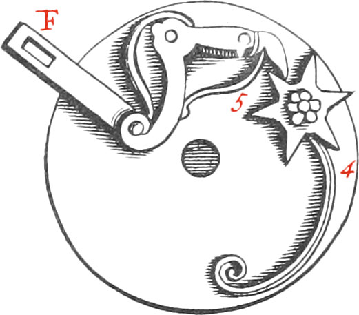
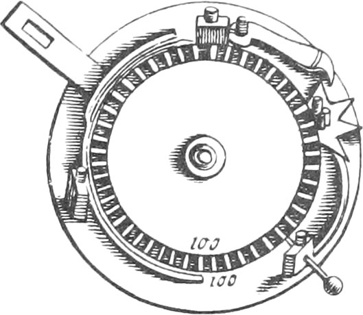
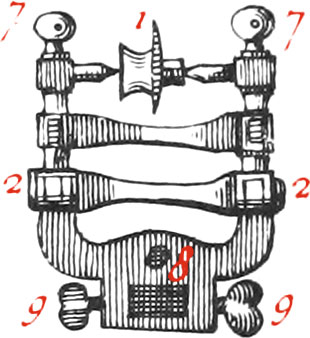
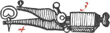
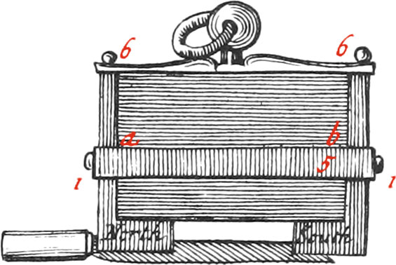
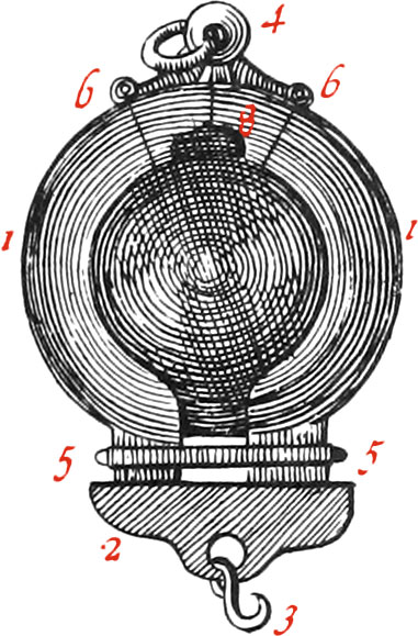
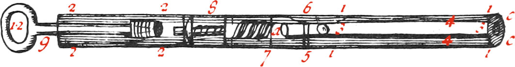
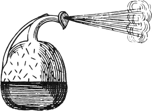
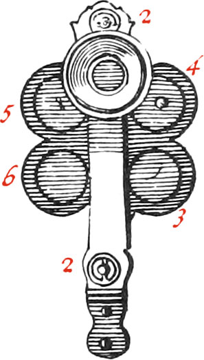
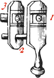
The Figures 6, 7, represent two armed Load-Stones; the first in the Form of a Parallelepipedon, and the second in the Form of a Sphere: But before we shew the bed way of arming them, we will enumerate some of the Properties and Virtues of Load-Stones.

The Load-Stone is a very hard and heavy Stone, found in Iron Mines, and is almost the Colour of Iron, for which reason it is reckoned among the Metallick Kind: it hath two wonderful Properties, one whereof is to attract Iron, and the other to direct itself towards the Poles of the World.

The Load-Stone attracts Iron, and reciprocally Iron attracts the Load-Stone, notwithstanding any other Body’s Interposition between them. This Stone likewise communicates to Iron a Faculty of attracting Iron: For Example, an Iron Ring that hath been touched with a good Load-Stone, will lift up another Iron Ring by only touching it, and this second a third, &c. but the first Ring must have a greater Degree of Attraction, than the second, and the second than the third, &c.

The Blade of a Knife that hath been touched with a Load-Stone, will likewise lift up Needles, and small Pieces of Iron: also several Sewing-Needles being laid upon a Table in a Row, and a Load-Stone being brought near the first, by which receiving the Magnetick Virtue, the said first Needle will attract the second, the second the third, &c. ’till they all come together.

That Iron reciprocally attracts the Load-Stone, when it can move freely, may be thus shewn: For if you put a Load-Stone into a hollow Piece of Cork, and set it floating upon the Surface of a Bason of Water, and bring a Piece of Iron at a convenient Distance to it, the Piece of Cork, together with the Stone, will accede to the Iron.

That Property of the Load-Stone which is always to respect the Poles of the World, may be shewn by the following Experiment: For having put a Load-Stone into a hollow Piece of Cork, and set them both a floating upon the Surface of still Water (there being no Iron, or other Obstacle near), the Load-Stone will always so dispose itself, that one certain Point thereof will regard the North, and the opposite Point the South.

But you must note, that the Load-Stone doth not exactly respect the North, it having at different Times, and in different Places of the Earth’s Superficies, different Declinations, or Variations therefrom, and at this time at Paris, varies 12 Deg. 15 Min. Westward: so that the South Pole of the Load-Stone varies above 12 Degrees from that of the World, and it’s Opposite so likewise. The Poles of a Load-Stone, are those two Places thereof, that respect the two Magnetick Poles of the World; and the principal Axis, is a right Line drawn from one Pole to the other, about which, the greatest Force of the Load-Stone manifests itself, and at the two Poles is greatest. Spherical Load-Stones have also ficted Equators, and Meridians, &c. from whence they are called Magnetick Spheres.

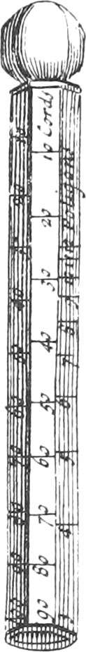
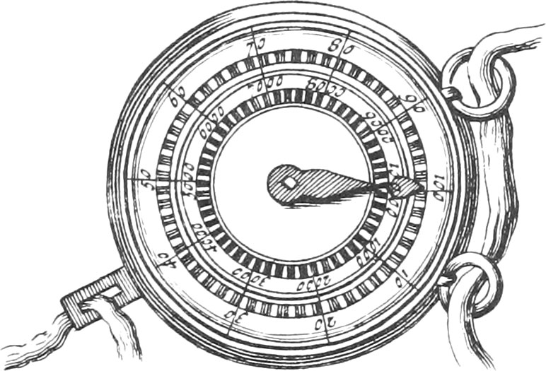
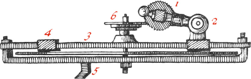
Now in order to find the Poles of a Load-Stone, you must cut a Hole in a Card of the Figure of the Stone, in which the Stone must be put, so that it’s principal Axis may be found in the Plane of the Card. This being done, Iron or Steel Filings must be strewed upon it: after which strike the Card softly with a little Stick, so that by putting the Filings in Motion, the Magnetick Matter may let them take a Circuit conformable to the way which that Matter takes in moving from a North Pore to another South one, and you will perceive the Filings ranged in the Figure of several Semi-Circumferences, whole opposite Ends are the Poles of the Load-Stone.

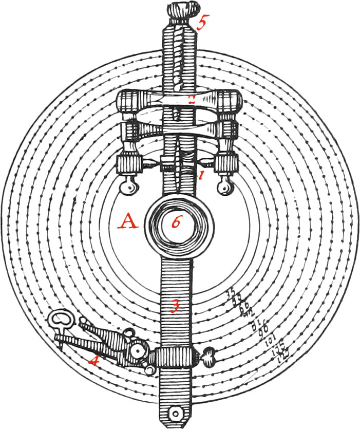
The Poles of a Load-Stone may otherwise be found, in plunging it into Iron or Steel Filings, or into very little Bits of Steel Wire; for then they will make different Configurations round the Stone, some of them lying flat on it, others half bent; and finally, others quite upright on it: and those Places of the Stone where the little Bits of Steel are perpendicular to it, are the Poles; and where they lie along, is the Equator.

Having thus found the Poles of a Load-Stone; which is the North or South Pole, may be known in laying the Stone in a hollow Piece. of Cork, swimming on Water, or by suspending it with a Thread, so that it’s Axis be parallel to the Horizon; for then that Pole of the Stone turning towards the North Pole of the World, will be the South Pole of the Stone, and the opposite Point the North Pole.

The Poles of a Load-Stone may likewise be found by means of a Compass; for bringing a touched Needle to the Stone, the End that was touched, will immediately turn towards that Pole of the Stone agreeing therewith, and the other End of the Needle will likewise turn towards the other Pole of the Stone.

The Poles of the Stone being found, the next thing will be to cut, and give it a regular Figure, in taking away the Superfluities either with a Saw, and Powder of Emery, or else with a Knife Grinder’s Grind-stone, preserving it’s Axis as long as possible, and giving a like Figure to it’s Poles.

Now to make a great many Experiments, it is necessary to give to a Load-Stone the most regular Figure possible, which is determined by the Likeness it hath to that of the irregular Mass it is composed of: the Cube, the Parallelepipedon, the Oval, and the Round are to be preferred, on account of having the principal Axis of the Stone as long as may be. If a Load-Stone is to be made in Form of a Sphere, it will not be difficult to find it’s Poles and Axis; you need only figure it with Powder of Emery in a round Iron Concave, and afterwards finish it with find Sand, in a round Brass Concave.

A Load-Stone in Figure of a Sphere, is very fit for many Experiments, and it’s Poles may be found in manner aforesaid: but it is necessary, before any pains be taken in cutting and figuring of a Load-Stone, to be assured of it’s Goodness, in observing whether it strongly attracts Filings, or little Bits of Steel; and whether there be not other Matter passing thro’ it’s Pores, which hinders the Magnetical Matter from circulating and passing from one Pole to the other.

The Goodness of a Load-Stone consists in two essential Things; which are, first, That it be homogeneous, having a great Number of Pores filled with Magnetick Matter, which passing thro’ them form about the Stone, as it were, a very extensive Whirlwind. In the second place, it’s Figure very much contributes to it’s Force (as we have already said), for it is certain, that of all Load-Stones of a like Goodness, that which hath the best Poles, it’s Axis longest, and whose Poles meet exactly in the Extremes, will be most vigorous.

Two Load-Stones placed in two hollow Pieces of Cork, which are both set floating upon the Surface of the Water, having their Poles of contrary Denominations turned to each other, will accede to each other; but if the Poles of the same Denomination be turned towards each other, then the Load-Stones will mutually recede from one another.

If a Load-Stone be cut into two Pieces, parallel to it’s Axis, the Sides of the Pieces that were together before the Division, will mutually recede from each other.

But if a Load-Stone be cut into two Pieces, according to it’s Equator, the Sides of the Pieces that were together before they were cut, will be found to have Poles of a contrary Denomination, and will accede to each other.
A strong Load-Stone touching a weak one, will attract it with it’s Pole of the same Denomination, &c.

The Description of the Armour, or Capping for Load-stones.

Fig. 6

The Armour for a Load-stone, cut into the Form of a right-angled Parallelepipedon, is composed of two square Pieces of very smooth Iron or Steel; but tempered Steel is better than Iron, because it’s Pores are closer, and there are a greater Number of them. Care must be taken, that the Armour well encompasses, and exactly touches the Poles of the Load-stone, and that the Armour is in Thickness proportionable to the Goodness of the Stone: for if strong Armour be put upon a weak Stone, it will produce no Effect, because the magnetick Matter will not have force enough to pass thro’ it; and, on the contrary, if the Armour of a strong Stone be too thin, it will not contain all the magnetick Matter it ought, and consequently the Stone will not produce so great an Effect, as when the Armour is thicker.

Now, to fit the Armour exactly, you must file it thinner by Degrees; and when you find the Effect of the Stone to be augmented as much as possible, the Armour will be in it’s just Proportion, and will have it’s convenient Thickness; after which it must be smoothed within Side, and polished without.

The Heads of the Armour (whereon is writ North and South) must be thicker than the other Parts, and cover about \(\frac{2}{3}\) of the Length of the Axis.

The Breadth and Length of the Armour, best fitting a Stone, may also be found by filing it by little and little; but, above all, Care must be taken that the two Heads are equal in Thickness, and that their Eases very exactly meet in the same Plane. Number 5 is a Brass or Silver Girdle fitted about the Stone, serving to fasten and hold the Armour, by means of two Screws 1, 1; and at 6 and 6 are two Screws fastening a round Brass Plate, carrying the Pendant 4, and it’s Ring, to the Top of the Armour.

Fig. 7

The Armour of a spherical Load-stone is composed of two Steel Shells, fastened to the Piece 8 by two Joints 6, 6; of a Girdle 5, 5; of a Pendant and Ring 4; and of a Piece (or Porte-Poid) 2, to hold the Hook 3 Great Care must be taken that the Shells very exactly join the Superficies of the Stone, and that they well encompass the Poles of the Stone, and cover the greatest part of the Convexity thereof. The convenient Breadth and Thickness of this Armour may be found by Trials, as before-mentioned.

It is very wonderful, that two little Pieces of Steel, composing the Armour of a Load-stone, should give it such a Property, that a good Stone, alter it is armed, will attract above 150 times more than before it was armed.

There are indifferent good Stones, which, unarmed, weigh about three Ounces, and will use up but half an Ounce of Iron; but being armed, will lift up more than seven Pounds.

To preserve a Load-stone, you must keep it in a dry Place among little Bits of Steel-Wire; for Filings, which are always full of Dust, make it rusty.

We sometimes suspend Load-stones, so that having the liberty to move, they may conform themselves to the Poles of the World; and if, in this Situation, the Piece carrying the Hook, or Porte-Poid, be put on, and the Weight the Stone commonly carries be hung on, and from time to time there be hung to it some small Weight more, you will find that, when the Stone has continued suspended some Days, that it will lift up a much greater Weight than it did before it was hung up.

Several common Experiments made with the Load-stone.

The first and usefullest Experiment made with the Load-stone, is that of touching the Needles of Sea-Compasses; for rightly doing of which, you must draw the Needle softly over one of the Poles of the Load-stone, from it’s Middle to it’s End, and then it will receive it’s Virtue. But, Note, that that End of the Needle, which hath been touched with one of the Poles of a Load-stone, will turn towards the opposite Part of the World, to that which that Pole regards; therefore it the End of a Needle is to turn towards the North, it must be touched with that Pole of the Stone respecting the South. Note, The longer Needles are, the less will they vibrate.

This admirable Direction of the Load-stone and Touched Needle hath not been known in Europe much above two hundred Years, by means of which, Navigation hath been almost infinitely advanced. But there is one Inconveniency, which is, that a Touched Needle doth not exactly respect the Poles of the World, but declines or varies therefrom towards the East or West, at different Times, and in different Places, variously. In the Year 1610, it varied at Paris 8 Degrees North-Easterly; in 1658, it had no Variation; and in the Year 1716, it varied about 12 Deg. 15 Min. Westward.

Moreover, the Needle hath also an Inclination as well as a Declination; that is, the Needle of a Sea-Compass being in Equilibrio upon it’s Pivot, will, when touched, lose that Equilibrium, and the End that turns North, on this side the Equator, will drip or incline towards the Earth, as if it was heavier on that Side; for which reason the North Side of a Needle must be made lighter, before the Needle be touched, than the South Side, and going towards the Poles, this Inclination grows greater; but in going towards the Equator, it grows lesser: so that under the Equator, the Inclination will be nothing; and in passing the Line, the other End of the Needle, respecting the South, will begin to incline; so that Pilots are obliged to stick as much Wax to the End of the Needle, as will make it in Equilibrio. Note, The greater Force that Load-stones, which touch Needles, have, the more will the Needles
There are Needles purposely made to observe this Inclination, which at Paris is about 70 Degrees.

It a long thin Piece of Steel be drawn over one of the Poles of an armed Load-done (in the same manner as was said before of the Needles), this Piece of Steel will in an instant acquire the magnetick Virtue, and will not lose it but by degrees after several Months, unless it be put in the Fire. Note, A Piece of Steel, touched by a good Stone, will lift up 14 Ounces.

The two Ends of a Steel Blade thus touched will become North and South Poles; that End whose Contact ends on the South Pole of the Stone, being the North, and the other the South Pole: for if this Piece of Steel be made light enough to swim, one End thereof will turn to the North, and the other to the South.

Again; that End of the Steel Blade where the Contact ended, will attract much stronger than the other End; and if the said Blade be once drawn over the Stone the contrary way, it will quite lose it’s Virtue, and attract no more. Understand the same of the Needle of a Compass, the Blade of a Knife, &c. two touched Steel Blades will avoid each other, and approach like two Load-stones.

A Piece of Steel, in a hollow Piece of Cork swimming on the Water, may be any ways moved, by bringing the Pole of a Load-stone towards it, or another touched Piece of Steel.

A fine Sewing-Needle, suspended by a Thread, will shew what is meant by Sympathy and Antipathy; for this Needle will be repelled by one Pole of a Load-stone, and attracted by the other.

A Needle may be kept upright, without it’s touching a Load-stone; so that there may be put between it and the Stone, a Piece of Silver, or other Matter, provided it be not Iron.

If, about a Load-stone, suspended by a String, be circularly placed several little touched Needles of a Compass, upon their Pivots, and the Load-stone be moved any how, you will likewise see all the Needles move in a pleasant manner; and when the Stone ceases moving, the Needles will also cease.

What we have already spoken about strewing of Filings about a Load-stone, may be said also of strewing them about a Piece of touched Steel.

If Filings be strewed upon a Piece of Pasteboard, and a Load-stone be moved under it, the Filings will erect themselves, and then lie along on that Side from whence the Stone came.

If, instead of Filings, you lay upon a Piece of Pasteboard several Bits of the Ends of broken Needles; by bringing one Pole of a Load-stone towards them, they will erect themselves upon one of their Ends; and by bringing the other Pole, they will fall, and rise upon their other Ends.

It is easy to separate a black Powder mixed with white Sand, and proposing it to a Person, not knowing the Secret, he will think it impossible; for if Iron Filings be mixed with fine Sand, they may be separated from it by a Load-stone, or Piece of touched Steel: for either of them being put into the Mixture, at divers times, you may get all the Filings from among the Sand.

A Load-stone will lift up a Whirlegig in Motion, whose Axis is Steel; and if it be something heavy, it will turn a longer Time in the Air than upon a Table, where the Friction soon stops it’s Motion; and if the Stone be a good one, this Whirlegig may lift up another, and both of them will turn contrary Ways. Another diverting Experiment may yet be made, by putting little Steel Fishes, or Swans, into a flat Bason of Water; for by moving a good Load-stone under the Bason, you will see them prettily swimming about; and moving the Stone different ways, they will likewise have different Motions; if the Stone be turned round, the Fishes will also turn round; if the Pole of the Stone be turned towards them, they will plunge themselves, as it were, to join themselves to the Stone. You may likewise put little Steel Soldiers into the Bason, which may be made to approach to, or recede from, each other in form of a Battel; and by bringing the Equator of the Stone towards them, they will fall down.

It is pleasant enough to see a Sewing-Needle threaded, or a little Arrow, fastened by a Hair to the Arc of a Cupid’s Bow, remain suspended in the Air eight or ten Lines distant from a good Load-stone.

There are several other Experiments made with the Load-stone, but mentioning them here would take up too much time.

The Construction of an Artificial Magnet.

Fig. 8

This Instrument, invented by Mr Joblot, is composed of several very strait Steel Blades laid upon one another; and to make it passably good, there ought to be at least 20 of them (according to the force of the Magnet to be made), each about 10 Inches long, 1 Inch broad, and half a Line in Thickness. It is useless to make them thicker, because the magnetick Virtue will not penetrate further into the Steel Blades.

Now these Blades being first touched with a good Stone, are afterwards laid one upon another, having their Poles, of the same Denomination, turned the same way, forming a Parallelepipedon; then they are pressed together with four Brass Stirrups, and as many little Wedges 3, 3, 3, 3, of the same Metal, and encompassed with Iron Armour of a proper Length, Breadth, and Thickness. This Armour is held by a Brass Girdle, and fastened with the Screws 2, 2. At the Top is placed a Brass Plate, to which is fastened the Pendant 4, and it’s Ring; and at the Bottom is the Port-Poids 5. But, Note, That the Base of the Porte-Poids must make the perfected Contact possible with the Heads a, b, of the Armour. When artificial Magnets are well made, and touched with good Stones, they will have as much Virtue in them as good natural ones, and may be used for the same Experiments.

The Construction of the Spring Steel-yard.

Fig. 9

This Machine, which is portable, and serves to weigh any thing from one Pound to about forty, is composed of a Brass Tube or Pipe, open at the Ends, about 4 or 5 Inches long, and 7 or 8 Lines broad, one End whereof is marked 3; the rest being open for shewing the Inside, which is a Spring (2) of tempered Steel-Wire, made like a Worm. Number 6. is a little Feril screwed upon the Top of the square Brass Rod 1, which the Spring crosses. Upon this Rod are the Divisions of Pounds, and Parts of a Pound, which are made in successively hanging on the Hook (4.) 1, 2, 3, &c. Pounds: for the Spring being fastened by a Screw to the Bottom of the square Rod, the greater the Weight is, that is hung on the Hook, the more will the Spring be contracted; and consequently a greater part of the Rod will come out of the Tube, thro’ the square Hole C: therefore if you have a mind to mark the Division for any Number of Pounds upon the Rod, suppose 10, hang 10 Pounds upon the Hook, and where the Edge of the square Hole C, at the Top of the Tube, cuts the Rod, make a Mark upon the Rod for 10 Pounds, and so for any other.

The Use of this Instrument is very easy; for having screwed the Feril 6 on the Top of the Rod, if you hold the Instrument in your Hand by the Hook 5, and hang any thing to be weighed upon the Hook 4; then where the Edge C of the square Hole cuts the Rod, will be the Weight of the thing required.

The chief Goodness of this Instrument consists in having a well-tempered Spring; so that it may fold according to the Force of the Weight it is to carry, and also in having a Bigness proportionable.

The Construction of the Beam Steel-yard.

Fig. 10

This Instrument, which is a kind of Steel-yard, or Balance of Mr Cassini’s Invention, consists of a Rod suspended by a Beam, in it’s Point of Equilibrium 5, which divides the said Rod into two Arms (like the two Arms of a common Balance) each of which are lengthwise divided into equal Parts, beginning from the Point of Suspension or Equilibrium.

The Use of this Balance is to find both the Weight and Price of Goods at the same time. If you use it for weighing any thing, the Counter-Weight 4 of one Pound, or one Ounce, must be hung to one of the Arms (according as Goods are to be weighed by Pounds or Ounces), so that it may slide along the Arm, like as in Roman Balances; and on the other Arm must be hung on a silken Line, for sustaining things to be weighed. Then to weigh any thing, you must place the silken Line, to which the thing is hung, upon the first Division of the Arm, nighest the Point of Equilibrium; and moving the Counter-weight upon the other Arm, ’till it makes an Equilibrium, the Point whereon it falls will show the Weight sought.

To know the Weight of Goods, according to any Price; for Example, at seven Pence an Ounce or Pound; place the Line, sustaining the Goods, upon the Division 7 of the Arm; then placing the Line, carrying the Counter-weight upon the other Arm, so that it be in Equilibrio, and the Number of Divisions, from the Point of Suspension to the Line sustaining the Counter-weight, will give the Value of the Goods weighed.

But for Goods that cannot be weighed, unless in a Scale, take a Scale of a known Weight, and having hung it upon a Hook to the Arm, proceed as before, and substract the Weight of the Scale.

A Paris Pound is 16 Ounces, and is divided into 2 Marks, each of which is 8 Ounces; an Ounce is subdivided into 8 Drams, a Dram into 72 Grains, and a Grain, which is nighly the Weight of a Grain of Wheat, is the least Weight used.

A Quintal weighs 100 Pounds.

The Paris Pound compared with those of other Countries.

  • The Pound of Avignon, Lyons, Montpelier, and Thoulouse is 13 Ounces.
  • The Pound of Marseilles and Rochelle is 19 Ounces.
  • The Pound of Rouen, Besançon, Strasburgh, and Amsterdam is 16 Ounces, like that of Paris.
  • The Pound of Milan, Naples, and Venice, is 9 Ounces.
  • The Pound of Messina and Genoa is 9\(\frac{1}{4}\) Ounces.
  • The Pound of Florence, Leghorne, Pisa, Sarragossa and Valence is 10 Ounces.
  • The Pound of Turin and Modena is 10 \(\frac{1}{2}\) Ounces.
  • The Pound of London, Antwerp and Flanders is 14 Ounces.
  • The Pound of Basil, Berne, Franckfort and Nuremburgh is 16 Ounces and 14 Grains.
  • That ef Geneva is 17 Ounces.

Construction of an Instrument for raising Weights.

Fig. 11

The Instrument of Fig. 11. consists of two Sheaves, each of which carries eight Pullies, hollowed in to receive a Rope, which is fastened at one End to the upper Sheave; and after having put it round all the Pullies, the other End of it must be joined to the Power represented by the Hand. Four of the Pullies are carried upon one Axel-Tree, and four upon another as well in the upper Sheave as in the lower one. At the Top of the upper Sheave is a Ring to hang the Machine in a fixed Place, and at the Bottom of the other, there is another Ring to hang the Weights to.

The Use of this Machine is to lift up or draw great Burdens, by multiplying the Force of the Power, which augments, in the Ratio of Unity, to double the Number of the Pullies in the lower Sheave; so that in this Instrument, where the lower Sheave carries eight Pullies, if the Weight (4) weighs 16 Pounds, the Power need be but a little above one Pound to make an Equilibrium; I say, a little above, because of the Friction of the Ropes and Axes. The Pullies of the upper Sheave do not at all contribute to the Augmentation of the Force, but only to facilitate the Motion in taking away the Friction of the Rope, because being as Leavers of the first kind, whose fixed Point is in the Middle, the Power will be equal to the Weight; but the Pullies below are as Leavers of the second Kind, whose fixed Point is at one of the Ends: for their Diameter is, as it were, fixed at one End, and lifted up at the other; by which each of the Pullies double their Force, since the way moved through by the Power, is double to that moved through by the Weight.

The Construction of the Wind-Cane.

Fig. 12

This Instrument is about three Foot long, and twelve or fifteen Lines in Thickness. The Tube 3 is made of Brass, very round, and well soldered, from 4 to 6 Lines in Diameter, stopped at one End a. At the Place 1 is likewise another larger Tube, so disposed about the former one, that there remains a Space 4, wherein the Air may be closely included. These two Tubes ought to be joined together at one End by a circular Plate c c, exactly soldered to them both, for hindering the Air’s getting out of the Space 4. The Piece 8 is a Valve stopping a Hole, permitting the Air to pass from 2 towards 1, but not to return from 1 towards 2. There are, moreover, two Holes near the stopped End of the Tube 3; thro’ one of these Holes, which is marked 6, the Air would come out of the Space 4 into the Tube 3, if it was not hindered by a Spring-Valve opening outwardly. The other Hole is marked 5, thro’ which there is a Communication with the outward Air, and the Air in the Cavity of the Tube 3; but yet so, that the Air, inclosed in the Space 4, cannot come out thro’ the Hole 5, it being hindered by a little short Tube soldered to the Tubes 1 and 3. Lastly, the Tube 2 represents the Body of a Syringe, by which as much Air as possible may be intruded into the Space 4; after which having put a Bullet into the Cavity of the Tube 3, near the little Tube 5, the Cane will be charged. Now, to discharge it, you must push up the Spring-Valve 6, by means of a little Pin exactly filling the Cavity of the little Tube 5; then the compressed Air, in the Cavity 4, will dilate itself; and passing thro’ the Hole 6, into the Cavity of the Tube 3, will push the Bullet out with a great force, even to it’s penetrating thro’ a Board of an ordinary Thickness.

Note, At Number 7 this Cane may be taken into two Pieces, by unscrewing of it; and the Handle 12 may be taken out, and instead thereof the Head of a Cane put thereon.

The Construction of the Æolipile.

Fig. 13

This Instrument is made of hammered Copper, in form of a Ball, or hollow Pear, having a Neck soldered to it, and a very little Hole drilled at the End of this Neck.

The Air in the Ball is first rarefied, by bringing it to the Fire; and afterwards plunging it into cold Water, will condense the Air in it, and the Water will pass thro’ the little Hole into the Cavity of the Instrument.

Now having let about as much Water, as will fill \(\frac{1}{3}\) of the Æolipile, get into it, if it be set upon a good Fire, in the same Situation as in the Figure, the Water, as it grows hot, will dilate itself by little and little, and throw up Vapours into the Space of Air contained between the Surface of the Water, and the little Hole at the End of the Neck, which, together with the Air, will very swiftly crowd thro’ the little Hole, and produce a Wind and violent Hiding, continuing ’till all the Water be evaporated, or the Heat extinguished. Note, This Wind has all the Properties of the natural Wind blowing upon the Surface of the Earth.

The Construction of four different Microscopes.

Fig. 14

This is a Microscope for viewing very minute Objects and Animals that are in Liquors. it is composed of two Plates of Brass, or other Metal, about 3 Inches long, and 8 Lines broad, fastened together, nigh the Ends, by two Screws, 2, 2, which likewise serve to fix the Plates at inch a Distance from each other, that a Wheel may turn which has six round Holes, in every of which are flat Pieces of Glass to put different Objects upon, marked 3, 4, 5, &c. Next to the Eye there is a concave Piece of Brass 1, having a Hole in the Middle, in which is put a very small Lens, or Ball of Glass. This Ball ought to be very convex, and well polished, in Order to distinguish minute Objects. The End of the Machine is filed in manner of a Handle to hold it.

The Use of this Instrument is very easy; if the Objects are transparent, as the Feet of a Flea, or of Flies, their Wings, the Mites in Cheese, or other minute Animals; as likewise Hairs of the Head, their Roots, &c. they are put upon the Glass Plates on the Wheel, and are held fast, with a little Gum-water: and to see the little Animals in stale Urine, Vinegar, in Water where there has been infused Pepper, Coriander, Straw, Hay, or almost any kind of Herbs; little Drops thereof must be taken up with the End of a little Glass Pipe, and laid upon the aforesaid Glasses: then the Wheel must be turned and raised, or depressed by means of the Screws 2, 2, and a Spring between the Plates, which serves to keep the Wheel in any Situation required, in such manner that a little Drop may be exactly under the Lens. Things being thus ordered, take the Microscope in your Hand, and having placed your Eye to the Concave 1, over the Lens, look steadily at the Drop in broad Day-light, or at Night by the Light of a Wax-Candle; at the same time turn the Screw at the End by little and little, to bring the Drop nigher, or make it further from the Lens, until the Point be found where the Object will be transparent, or the Animals swimming in the Drop of Liquor, appear very large and distinct.

The Construction of another Microscope.

Fig. 15

This Microscope is composed of a Brass Plate about three Inches high, and \(\frac{1}{2}\) an Inch broad, cut in Form of a Parallelogram, at the Bottom of which there is a Handle to hold it. The Place marked 1, is a little Groove drilled thro’ the Middle, in the Hole of which is placed a Lens fastened in a little Frame; there may be put into it Lenses of diverse Foci, according to the different Objects to be observed. Note, That the Focus of a Glass, is it’s Distance from the Object, and that Lenses are used in these Microscopes, whose Foci are from half a Line to four Lines.

On the Backside of the aforesaid Plate (at the Place 2.), is fixed a little square Branch of Brass or Steel, carrying another Plate that Aides upon it by means of a little Box, a Spring, and a Screw, turned by help of a Wheel, cut into Teeth, which serves to bring the said Plate nigher to, or more distant from that which carries the Lens. Towards the Top of the second Plate; which has a Hole drilled in it, is also a Groove, in which is placed little Pieces of plain Glass, and round Concaves to put Liquors on. There may be different Glasses put in that Groove for viewing different Objects. Lastly, Observe that all the Objects answer to the Center of the Lens, and that there must be adjusted on the other Side of the Plate a little Tube (marked 3.) of Brass, about an Inch Diameter, and one or two long, whose Center must, very exactly answer to the Center of the Lenses. It has been found that with such a Tube, these Microscopes will have much more effect upon transparent Objects, than without it. The Circulation of the Blood may pretty distinctly be observed in the Tails of little Fishes by this Microscope, which is, in my Opinion, the most commodious of any.

The Use of this Instrument is very easy; for having placed the Object over-against the Center of the Lens, move it backwards and forwards by means of the Screw, ’till it be seen very distinctly.

Construction of a single Glass Microscope.

Fig. 16

The little Instrument of Fig. 16. is a Microscope commodious enough, composed of a Branch of Brass, or other Metal, having a Motion towards the Top, for putting it into the Situation as per Fig. The Piece, at the End, carries a very convex Lens, magnifying the Object very much: this Branch is screwed into a little Box 5, bored through the Bottom. The Piece 4, is two Springs fastened to one another in the Middle with a Rivet, to give it a Motion desired. The Branch which carries the Lens, is put through one of the Springs; and through the other there is put a little Branch, carrying at one End the Piece 2, which is white on one Side, and black on the other, for different Objects. The other End 3, is a little kind of Pincer, which opens by pressing two little Buttons; it serves to hold little Animals, or other Bodies. The Foot 5, is about 1\(\frac{1}{2}\) Inch in Diameter, the Branch screws into it, in order to take to pieces the Instrument.

The Use of it is very easy, for the Objects being placed upon the little round Piece, or at the End of the Pincer, you must bring the Lens towards them, by sliding the Spring along the Branch, ’till the Objects be seen very distinct.

There may likewise be discovered with this Microscope, the Animals which are in Liquors, by putting a flat Glass in the Place of the little round Piece 2, which unscrews.

Construction of a Three-Glass Microscope.

Fig. 17

This Instrument is composed of three Glasses, viz. the Eye Glass 3, the Middle Glass 4, and the Object Lens 5. There is a Cover screwed on at the Top to preserve the Eye Glass from Dust: these three Glasses are set in wooden Circles, and screwed into their Places, for easier taking them out to cleanse. The Eye Glass, and the Middle one, are placed at the Ends of a Tube of Parchment, exactly entering into the outward Tube, in order to lengthen the Microscope, and place it at it’s exact Point, according to a Line drawn round about the aforesaid Tube. To have this Instrument of a reasonable Bigness, the focal Distance of the Eye Glass ought to be about 20 Lines, that of the middle Glass about 3 Inches, and placed about a Inches 2 Lines distant from one another.

The Object Lens is placed at the End of a wooden Tail-piece, glued to the End of the outward Tube, and is enclosed in a little Box, bored through the Bottom, which unscrews in order to change the Object Lenses, and put in others of different focal Distances, which are commonly 2, 3, 4, and 5 Lines in Diameter, and are more or less convex. The Goodness of these Glasses consists in having the concave Brass Basons they are ground in, turned in a just. Proportion to the Glasses to be worked; as also in the Motion of the Hand, and the Goodness of the Matter used to construct them, and above all in well polishing them. Brown Freestone is first used to fashion them in the Bason, then fine Sand to smooth them, and Tripoli to polish them. I shall say no more of the Construction of these Glasses, M. Cherubin having sufficiently spoken thereof.

The Foot 1, which ought to be pretty heavy to keep the Microscope from falling, is made of Brass 4 or 5 Inches in Diameter, having a Cavity in the Middle, wherein is put a little Piece, white on one Side, and black on the other: black Objects are placed upon the white Side, and white Objects upon the black Side.

The round Brass Branch is fastened at the Edge of the Foot, upon which the Microscope may Hide up or down, and turn round by means of the Support or double Square 2: there is a Circle, or Ring, strongly fastened to the Support, and which very exactly encompasses the outward Tube. There is also a Steel Spring which bears against the Branch, and keeps the Instrument in a required Situation.

Number 6, is a little Brass Frame, having in it a Piece of flat Glass to lay transparent Objects upon. This Frame may slide Up and down the Branch underneath the Microscope, and is supported by a double Square.

Lastly, Number 7 is a convex Glass converging the Rays of Light, coming from a Candle under it; and throwing them strongly under the transparent Object on the Glass, makes it be seen more distinctly. The aforesaid Glass is set in a Brass Circle, and rises, falls, and turns by means of a little Arm carrying it, as the Figure shews.

Use of the aforesaid Microscope.

To use this Instrument, for Example, to observe the Circulation of the Blood in some Animal; a live Fish must be placed upon the Glass 6, so that one part of the Fins of the Tail be exactly opposite to the Object Glass, and over the Ray of the Convex-Glass in broad Daylight, or the Spot of the Candle, in the Night; then place the Microscope exactly to such a Point, and you will see the Blood rise, descend, or circulate.

Number 9, is a little Piece of Lead hollowed, to keep the Fish from any how stirring to hinder the Experiment.

Liquors may also by this Microscope be very well examined; for if you put a little Drop of Vinegar upon the Glass just over the bright Spot; the little Animals in it will very distinctly be observed. The same may be observed of Water in which Pepper or Barley has been infused, &c. as also the Eels and other little Animals observed in standing Water.

A Drop of Blood may be observed by putting it hot over the Speck of the Candle, upon the Glass; after which it’s Serosity, and little Globules of a reddish Colour, may be discovered therein.

The best way to get a Drop of Blood is to tie a Thread about one’s Thumb, and then prick it with a Needle.

The best way to put Liquors upon the Glass, is by taking a Drop of them up with the small End of a little Glass Tube; and then blowing softly at the other End, will make the Liquor descend and drop upon the Glass.

To get a great Number of little Eels in a small Quantity of Liquor; the Liquor must be put into a very narrow-necked Bottle, and always kept full; for by this means, the Animals coming to the Top to get Air, may be sucked into a little Tube in greater Numbers, than if the Neck of the Bottle was wider.

The Eyes of Flies, Ants, Lice, Fleas, and Mites, are put in the Middle of the Foot of the Microscope, as also Sand, Salt, &c. to examine their Colours and Qualities; always observing to lay black Objects upon the white, and white Objects upon the black Side.

I suppose here that the Microscope Glasses are well worked, and placed in their Foci. Note also, that the shorter the Focus of an Object Glass is, the greater will the Object appear, but not altogether so distinct.

  1. Previous Book III. Chapter I. Compasses
  2. Contents
  3. Next Book IV. Chapter I. Staffs, Lines, Fathom or Toise, and Chain