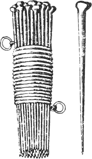
Staffs are made of hard Wood, 2 or 3 Foot long, cut pecked at one End, upon which are put pointed Caps of Iron, to make them go easier into the Ground. There are sometimes longer ones made, in order to be seen at a great distance.
Book IV.
Ch. I.
Containing the Description and Uses of Staffs, Lines, the Fathom or Toise, and the Chain.
Lines ought to be of good Packthread, or Whipcord, well twitted, and of a convenient Thickness, that they may not easily stretch.

The Toise, or Fathom, is a round Staff 6 Foot long, divided into Feet by little Rings, or Brass Pins; the last Foot being divided into 12 Inches, likewise distinguished by little Brass Pins.

There are Toises that may be taken into 2, 3, or 4 Pieces, by means of Ferils and Brass Screws at the End of each Piece.
There are also two Brass or Steel Ferils, put upon each End of the Toise, to preserve it’s Length.
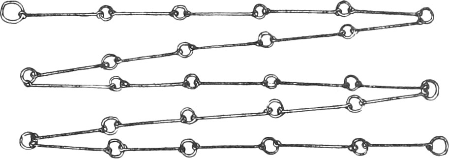
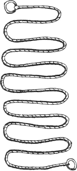
The Chain is composed of several Pieces of thick Iron or Brass Wire, bent at the Ends, each of which is a Foot long, and are joined together with little Rings.
Chains are commonly a Perch, or else 4 or 5 Toises in Length, distinguished by a great Ring from Toise to Toise. These sort of Chains are very commodious, because they will not entangle themselves, as those will that are made with little Iron Rings.
In the Year 1668, there was placed a new Toise for a Standard, at the Foot of the Stairs of the Grand Chatelet at Paris, for having recourse to in case of Need.
We have said that a Toise in Length contains 6 Feet, and each Foot 12 Inches. A square Toise contains 36 square Feet, and a square Foot 144 Inches; because 6 times 6 is 36, and 12 times 12 is 144.
A Cubick Toise contains 216 Cubick Feet, and a Cubick Foot 1728 Cubick Inches; because the Cube of 6 is 216, and the Cube of 12 is 1728.
The Length of a Perch is not determined.
That of Paris is 3 Toises, or 18 Feet; in other Countries it is 20, 22, and 24 Feet.
The Perch, used in France, to measure Waters and Forests, according to the last Regulation, is 22 Feet long, and consequently a square Perch is 484 square Feet.
The Arpent is a superficial Measure, used to measure Ground or Woods.
The Arpent of Paris, and the adjacent Parts, contains 100 square Perches, or 900 Toises; the Side of which must consequently be 10 Perches, or 30 Toises.
A League is a Measure for Highways, or great Distances; it's Length is not determined, being different in different Countries.
It is reckoned from the Gate of Paris, nigh the Grand Chatelet, to the Gate of the Church of St Dennis, 2 Leagues, each of which is 2200 Toises.
The Gentlemen of the Academy of Sciences have found, that a Degree of a great Circle of the Earth contains 57060 Toises; and giving 25 Leagues to a Degree, each League will contain 2282 Toises.
A Sea-League is greater, for there goes but 20 to make a Degree; therefore it contains about 3000 Toises.
The Italians reckon by Miles, each of which contains 1000 Geometrical Paces.
A Geometrical Pace is five of the antient Feet, one of which the antient Roman Palm is three quarters, which may be esteemed about 11 of our Inches; and consequently an Italian Mile contains about 769 of our Toises.
The Germans also reckon by the Mile, but they are much greater than the Italian Miles 1 for one or them contains 3626 Toises.
They count by Leagues in Spain, one of which contains 2863 Toises, 20 of which exactly make one Terrestrial Degree.
The same may be laid of the English and Dutch Leagues.
Use I. To draw a right Line thro’ two Points given upon the Ground, and produce it to any required Length.
Plant a Staff upon each of the given Points, very upright, and having drained a Line from one Staff to the other; by that Line, as a Guide, draw a Line upon the Ground.
That right Line may be continued by planting a third Staff, so that by placing the Eye to the Edge of the first, the Edges of the two others may be but just seen; and again, the Line may be continued, by taking that Staff, which was the first, and placing it as a third, &c.
Use II. To measure a right Line upon the Ground.
When a long Line upon the Ground is to be measured, Precaution must be used that we do not mistake, and be obliged to begin again. To do which, two Men must each of them have a Toise; the first having laid down his, must not lift up, ’till the second has placed his at the end of the first Man’s Toise. The first Man having lifted up his Toise, must loudly count 1; and when he has again laid his down to the End of the second Man’s, the second Man must lift up his, and count 2. In thus continuing on to the End, and in order to lay the Toises in a right Line, there must be placed to Staffs, at the Distance before them, to look at; for if there is but one, the Toises cannot be so truly laid in a right Line by the help of it.
To spare Time and Pains, you ought to have a Chain of 30 Feet, or 5 Toises long, with a Ring at each End, carried by two Men, the first of which carries several Staffs. When the Chain is well extended on the right Line to be measured, the foremost Man must place a Staff at the End of 5 Toises, to the end that the hinder Man may know where the Chain ended; for the whole Matter consists in well counting, and exactly measuring.
Use III. From a Point given in a right Line, to raise a Perpendicular.
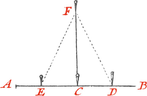
Let the given Line be AB, and the given Point C.
Plant a Staff in the Point C, and two others, as E, D, in the same Line, equally distant from Point C; then fasten the two Ends of a Line to the two Staves E, D, and fold the Line into two equal Prats in F; afterwards stretch the Line tight, and at the Point F plant a Staff, and the line FC will be perpendicular to AB.
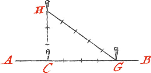
Otherwise; measure 4 Feet, or 4 Toises, from the Point C, on the Line AB, and the plant there the Staff G; take a Line containing 8 Feet, or 8 Toises (according as the former are Feet or Toises) fasten one End of the Line to the Staff C, and the other to the Staff G; then stretch the Line, so that 3 of those Parts be next to the Point C, and 5 next to G; plant a Staff in H, and the line HC will be perpendicular to AB.
Use IV. From a given Point without a Line, to draw a Perpendicular.
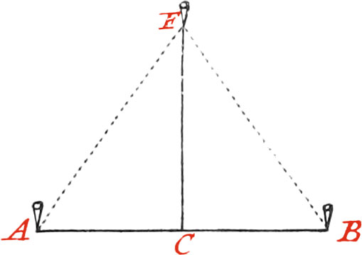
Let the given Line be AB, and the Point F.
Fold your Line into two equal Parts, and fix the Middle to the Staff F; stretch the two Halves (which I suppose long enough) to the Line AB; then plant two Staffs, namely, one to each End of your Line, and divide their Distance into two equal Parts, which may be done by folding a Line as long as the Distance AB; plant a Staff in the middle C, and the Line CF will be perpendicular to the Line AB.
Use V. To draw a Line parallel to another, at a given Distance from it.
Let the given Line be AB, and it is required to draw a Line parallel to it at the Distance of 4 Toises.
Raise (by Use 3.) two Perpendiculars, each of 4 Toises, upon the Points A, B; and upon the Points C, D plant two Staffs; by which draw the Line CD, which will be parallel to AB.
Use VI. To make an Angle on the Ground, at the End of a Line, equal to an Angle given.
Let ABC be the given Angle (which suppose is drawn upon Paper).
About the Point B, as a Center, describe upon the Paper the Arc AC, and draw the right Line AC, which will be the Chord of the said Arc. Measure with a Scale, or the Line of equal Parts of the Sector, the Length of one of the equal Legs AB, or BC of the said Angle; likewise measure, with the same Scale, the Length of the Chord AC; which, for Example, suppose 36 of those equal Parts, whereof the Leg AB contains 30.
Now let there be upon the Ground a right Line, as BC, to which it is required to draw another Line FB, making an Angle with BC equal to the proposed one. Plant a Staff in the Point B, and having measured 30 Feet, or 5 Toises, on the Line BC, there plant a Staff, as D; then take two Lines, one of 30 Feet long, which fasten to the Staff B, and the other 36 Feet, which likewise fasten to the Staff D: Draw the Lines tight, and make their Ends meet in the Point F, where again plant a Staff, from which draw the Line FB; which will form, at the Point B, the Angle FBC equal to the proposed one ABC.
Use VII. To draw upon Paper an Angle, equal to a given one upon the Ground.
This Problem is the Converse of the former.
Let the given Angle upon the Ground be FBC; measure 30 Feet, or 5 Toises, from B towards C, at the End of which plant the Staff D; measure likewise 30 Feet from B towards F, and there plant another Staff; measure also the Distance of the Staffs F, D, which suppose will be 36 Feet (as in Use VI.).
Now let BC be a Line upon the Paper; then about the Point B, as a Center, and with a Length of 30 equal Parts (taken from a Scale) describe the Arc AC; and take 36 of the same Parts, and lay them off from the Point C, upon the Arc CA, and a Line drawn from B to A will make, with the Line BC, the Angle required.
If, moreover, the Quantity of the aforesaid Angle be desired, it will be found, by the Protractor, something less than 64 Degrees.
The Quantity of Angles (whose Chords are known), in Degrees and Minutes, may more exactly be known by the following Table, which is calculated for Angles, always contained under equal Sides of 30 Feet each.
The Use of the said Table is very easy for finding the Quantity of any Plane Angles upon the Ground: for measure 30 Feet upon each of the Lines forming an Angle, and plant a Staff at the End of 30 Feet upon each Line; then measure the Distance between the two Staffs, which suppose to be 36 Feet (as in the preceding Example), look in the Table in the Column of Bases of 36 Feet, and you will find over against it, in the Column of Angles, 63 Degrees, 44 Minutes, the Quantity of the said Angle.
- 2 0° 19′
- 4 0° 38′
- 6 0° 57′
- 8 1° 8′
- 10 1° 36′
- 1 1° 55′
- 2 2° 14′
- 4 2° 33′
- 6 2° 52′
- 8 3° 11′
- 10 3° 30′
- 2 3° 49′
- 2 4° 8′
- 4 4° 28′
- 6 4° 47′
- 8 5° 6′
- 10 5° 25′
- 3 5° 44′
- 2 6° 3′
- 4 6° 22′
- 6 6° 41′
- 8 7° 0′
- 10 7° 20′
- 4 7° 39′
- 2 7° 58′
- 4 8° 17′
- 6 8° 36′
- 8 8° 55′
- 10 9° 14′
- 5 9° 34′
- 2 9° 53′
- 4 10° 12′
- 6 10° 31′
- 8 10° 50′
- 10 11° 9′
- 6 11° 29′
- 2 11° 48′
- 4 12° 8′
- 6 12° 27′
- 8 12° 46′
- 10 13° 5′
- 7 13° 24′
- 2 13° 43′
- 4 14° 2′
- 6 14° 22′
- 8 14° 41′
- 10 15° 0′
- 8 15° 20′
- 2 15° 39′
- 4 15° 58′
- 6 16° 18′
- 8 16° 37′
- 10 16° 56′
- 9 17° 15′
- 2 17° 34′
- 4 17° 54′
- 6 18° 13′
- 8 18° 32′
- 10 18° 52′
- 10 19° 11′
- 2 19° 30′
- 4 19° 50′
- 6 20° 19′
- 8 20° 29′
- 10 20° 48′
- 11 21° 8′
- 2 21° 27′
- 4 21° 46′
- 6 22° 16′
- 8 22° 25′
- 10 22° 45′
- 12 23° 6′
- 2 23° 24′
- 4 23° 44′
- 6 24° 3′
- 8 24° 23′
- 10 24° 42′
- 13 25° 1′
- 2 25° 21′
- 4 25° 41′
- 6 26° 1′
- 8 26° 20′
- 10 26° 40′
- 14 26° 53′
- 2 27° 18′
- 4 27° 38′
- 6 27° 58′
- 8 28° 18′
- 10 28° 38′
- 15 28° 57′
- 2 29° 17′
- 4 29° 37′
- 6 29° 56′
- 8 30° 16′
- 10 30° 36′
- 16 30° 56′
- 2 31° 16′
- 4 31° 36′
- 6 31° 56′
- 8 32° 16′
- 10 32° 35′
- 17 32° 55′
- 2 33° 15′
- 4 33° 35′
- 6 33° 55′
- 8 34° 15′
- 10 34° 35′
- 18 34° 55′
- 2 35° 15′
- 4 35° 35′
- 6 35° 55′
- 8 36° 15′
- 10 36° 35′
- 19 36° 55′
- 2 37° 15′
- 4 37° 36′
- 6 37° 56′
- 8 38° 16′
- 10 38° 35′
- 20 38° 56′
- 2 39° 17′
- 4 39° 38′
- 6 39° 58′
- 8 40° 18′
- 10 40° 38′
- 21 40° 59′
- 2 41° 19′
- 4 41° 40′
- 6 41° 0′
- 8 42° 20′
- 10 44° 40′
- 22 43° 1′
- 2 43° 22′
- 4 43° 42′
- 6 44° 3′
- 8 44° 24′
- 10 44° 44′
- 23 45° 5′
- 2 45° 26′
- 4 45° 46′
- 6 46° 7′
- 8 46° 28′
- 10 46° 48′
- 24 47° 9′
- 2 47° 30′
- 4 47° 51′
- 6 48° 12′
- 8 48° 33′
- 10 48° 54′
- 25 49° 15′
- 2 49° 36′
- 4 49° 57′
- 6 50° 18′
- 8 50° 39′
- 10 51° 0′
- 26 51° 21′
- 2 51° 42′
- 4 52° 3′
- 6 52° 24′
- 8 52° 46′
- 10 53° 8′
- 27 53° 29′
- 2 53° 51′
- 4 54° 12′
- 6 54° 34′
- 8 54° 55′
- 10 55° 18′
- 28 55° 38′
- 2 56° 0′
- 4 56° 22′
- 6 56° 43′
- 8 57° 5′
- 10 57° 26′
- 29 57° 48′
- 2 58° 10′
- 4 58° 32′
- 6 58° 54′
- 8 59° 16′
- 10 59° 38′
- 30 60° 0′
- 2 60° 22′
- 4 60° 44′
- 6 61° 6′
- 8 61° 28′
- 10 61° 50′
- 31 62° 13′
- 2 62° 35′
- 4 62° 58′
- 6 63° 20′
- 8 63° 43′
- 10 64° 5′
- 32 64° 28′
- 2 64° 50′
- 4 65° 13′
- 6 65° 36′
- 8 65° 58′
- 10 66° 21′
- 33 66° 44′
- 2 67° 7′
- 4 67° 30′
- 6 67° 53′
- 8 68° 16′
- 10 68° 39′
- 34 69° 2′
- 2 69° 25′
- 4 69° 48′
- 6 70° 12′
- 8 70° 35′
- 10 70° 59′
- 35 71° 22′
- 2 71° 46′
- 4 72° 10′
- 6 72° 33′
- 8 72° 56′
- 10 73° 20′
- 36 73° 44′
- 2 74° 8′
- 4 74° 32′
- 6 74° 56′
- 8 75° 20′
- 10 75° 44′
- 37 76° 9′
- 2 76° 33′
- 4 76° 57′
- 6 77° 22′
- 8 77° 46′
- 10 78° 9′
- 38 78° 35′
- 2 79° 0′
- 4 79° 25′
- 6 79° 50′
- 8 80° 15′
- 10 80° 40′
- 39 81° 5′
- 2 81° 30′
- 4 81° 55′
- 6 82° 20′
- 8 82° 46′
- 10 83° 12′
- 40 83° 37′
- 2 84° 3′
- 4 84° 29′
- 6 84° 54′
- 8 85° 20′
- 10 85° 46′
- 41 86° 13′
- 2 86° 39′
- 4 87° 5′
- 6 87° 32′
- 8 87° 58′
- 10 88° 25′
- 42 88° 51′
- 2 89° 18′
- 4 89° 45′
- 6 90° 12′
- 8 90° 39′
- 10 91° 6′
- 43 91° 33′
- 2 92° 1′
- 4 92° 29′
- 6 92° 56′
- 8 93° 24′
- 10 93° 52′
- 44 94° 20′
- 2 94° 48′
- 4 95° 16′
- 6 95° 20′
- 8 96° 13′
- 10 96° 42′
- 45 97° 11′
- 2 97° 40′
- 4 98° 9′
- 6 98° 38′
- 8 99° 8′
- 10 99° 37′
- 46 100° 6′
- 2 100° 36′
- 4 101° 6′
- 6 101° 36′
- 8 102° 7′
- 10 102° 37′
- 47 103° 8′
- 2 103° 39′
- 4 104° 10′
- 6 104° 41′
- 8 105° 12′
- 10 105° 44′
- 48 106° 16′
- 2 106° 48′
- 4 107° 20′
- 6 107° 52′
- 8 108° 25′
- 10 108° 57′
- 49 109° 30′
- 2 110° 4′
- 4 110° 37′
- 6 111° 11′
- 8 111° 44′
- 10 112° 18′
- 50 112° 53′
- 2 113° 28′
- 4 114° 3′
- 6 114° 38′
- 8 115° 14′
- 10 115° 49′
- 51 116° 26′
- 2 117° 2′
- 4 117° 39′
- 6 118° 16′
- 8 118° 53′
- 10 119° 31′
- 52 120° 9′
- 2 120° 47′
- 4 121° 26′
- 6 122° 6′
- 8 122° 45′
- 10 123° 25′
- 53 124° 6′
- 2 124° 47′
- 4 125° 28′
- 6 126° 10′
- 8 126° 42′
- 10 127° 35′
- 54 128° 19′
- 2 129° 3′
- 4 129° 48′
- 6 130° 33′
- 8 131° 19′
- 10 132° 6′
- 55 132° 53′
- 2 133° 44′
- 4 134° 30′
- 6 135° 20′
- 8 136° 11′
- 10 137° 3′
- 56 137° 57′
- 2 138° 49′
- 4 139° 44′
- 6 140° 40′
- 8 141° 38′
- 10 142° 36′
- 57 143° 36′
- 2 144° 39′
- 4 145° 43′
- 6 146° 48′
- 8 147° 57′
- 10 149° 8′
- 58 150° 20′
- 2 151° 36′
- 4 152° 55′
- 6 154° 19′
- 8 155° 48′
- 10 157° 22′
- 59 159° 3′
- 2 160° 53′
- 4 162° 54′
- 6 165° 12′
- 8 167° 48′
- 10 171° 28′
- 60 180° 0′
Note, That in the Columns of Bases are only set down every 2 Inches, and the Feet from 1 to 60. By means of this Table may be easily and exactly found the Opening and Quantity of any Angle; for suppose your Base be in Length 50 Feet, 3 Inches, and the other 2 Sides each 30 Feet, which they must always be. Seek 50 Feet, 2 Inches, in the Column of Bases; and against it you will find, in the Column of Angles, 113 Deg. 28 Min. whence by making due Proportion with the Inches and Minutes, the Quantity of the Angle sought will be 113 Deg. 44 Min. This Table, together with a well divided Brass Scale, may be used in measuring or laying off Angles upon Paper, with as much Exactness as Lines will do them upon the Ground; because the Sides of equiangled Triangles are proportional to each other.
This Method of measuring plane Angles, may likewise serve to make Designs of Fortification, both regular and irregular, to find the Quantities of Angles, as well of Bastions as of the Polygon, formed by the Concourse of the Lines of the Bases, or exterior Sides, either upon Paper or the Ground.
To draw Angles by this Table, seek for the Degrees and Minutes you design an Angle to consist of, which, for Example, suppose 54 Deg. 34 Min. and against them, in the Column of Bases, is the Number of Feet and Inches corresponding thereto, viz. 27 Feet, 6 Inches; which is the Length of the Base of the Angle, each of the other Sides of which is 30 Feet, and so of others.
Use VIII. To take the Plane, or Plot of a Place within it.
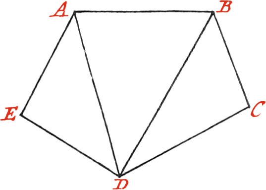
Let the Place whose Plan is required, be ABCDE.
First, make a Figure upon your Paper, something like the Plan to be taken, and after having measured with a Toise the Sides AB, BC, CD, DE, and EA, write the Lengths found upon each of their corresponding Lines on the Paper; then instead of measuring the Angles made by the Sides, measure the Diagonals AD, BD, which write down in your Book, and the Figure will be reduced into three Triangles, whose Sides are all known, because they have been actually measured. Then the Figure must be drawn neat in your Book by means of a Scale of equal Parts.
Note, Of all the Ways to take the Planes of Places, that of taking it within is the best.
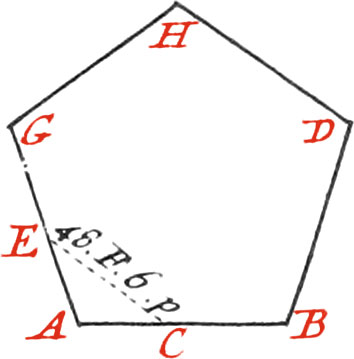
Use IX. To take the Plot of any Place (as a Wood, or marshy Ground) by measuring round about it.
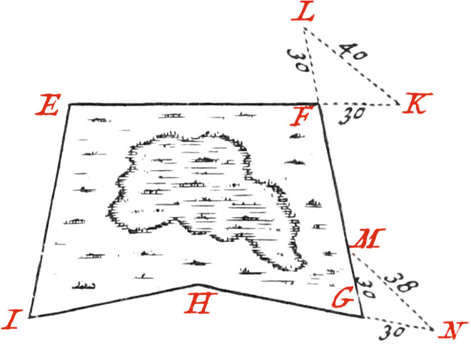
First draw a rough Sketch of the Figure in your Field-Book: if it takes not too much time in going round the Place; then measure with a Toise, or Chain, all the Sides encompassing the Figure proposed, and set the Numbers found upon each correspondent Line, in your Book; but for the Angles, you must measure them as follows.
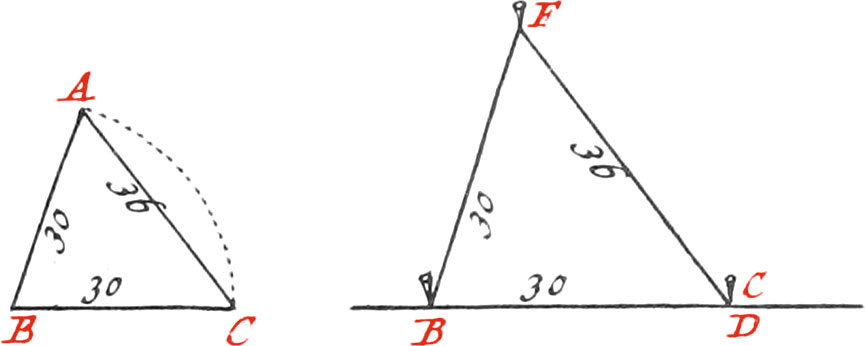
To measure, for Example, the Angle EFG, produce the Side EF, 5 Toises, and plant a Staff at the End K; produce also the Side GF, the Length of 5 Toises, and plant a Staff at the End L. Measure the Distance LK, and supposing it 6 Toises, 4 Feet, that is 40 Feet, set it down upon the Line LK in your Book, by which means the three Sides of the Isosceles Triangle LFK will be had; and consequently the Angle LFK, may be known by the aforementioned Table, or otherwise. Now the aforesaid Angle is equal to it’s opposite one EFG, and if you seek 40 Feet in the Column of Bases, the Angle will be found 83 Deg. 37 Min.
In the same manner may the Angle FGH, or any other of the proposed Figure, be measured: or else thus, Produce the Side HG, the Length of 5 Toises, to N, where plant a Staff; make likewise GM, 5 Toises. Measure the Distance MN, which suppose, for Example, 6 Toises, 2 Feet, or 38 Feet, which write upon the Line MN in your Book.
This Number sought in the Column of Bases, corresponds to 78 Deg. 35 Min. for the exterior Angle MGN, whose Complement 101 Deg. 25 Min. is the Quantity of the Angle FGH.
Then the Figure in your Field-Book must be drawn neat by means of a Scale of equal Parts, as well to denote the Lengths of the Sides, as the Bases of all the Angles, which may exactly be had without the Trouble of taking their Quantities in Degrees and Minutes.
Use X. To draw any regular Polygon upon a given Line on the Ground.
Let, for Example, the given Line be AB, upon which it is required to make an equilateral Triangle.
Measure 30 Feet upon the Line AB, from A to D, where plant a Staff: then take 2 Lines, each 30 Feet long, one of which fasten to the Staff D, and the other to the Staff A, and stretch them ’till their Ends join in the Point C, where plant another Staff.
Make the same Operation at the other End of the given Line, and produce the Lines AC, and BF, ’till they meet in the Point E, and form the equilateral Triangle AEB required.
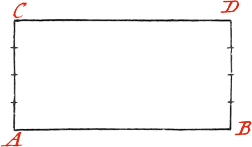
If a Square be to be made upon the given Line AB, raise upon each End A and B, a Perpendicular (by Use III.).
Then make each of those Perpendiculars equal to the Line given, plant Staffs at their Ends C and D, and draw the Line CD, which will compleat the Square proposed.
If a Pentagon is required to be drawn upon the given Line AB:
You will find that the Angles formed by the Sides of a Pentagon, are each 108 Degrees; (as before has been said, in Use 3. of the Protractor, and in the third Section, concerning the Line of Polygons of the Sector); therefore seek for, in the Table of Plane Angles, the Number that answers to 108 Degrees, or nighly approaches it, and you will find 48 Feet, and something above 6 Inches: for that Number answers to 107 Deg. 52 Min. which is lesser by 8 Min. than 108 Degrees; whence 48 Feet, 6\(\frac{1}{2}\) Inches, may be taken for the aforesaid Base.
Now measure upon the given Line, from the Point A towards B, 30 Feet, and plant a Staff in the Point C, where the said Length terminates: then take 2 Lines, one 30 Feet, the End of which fasten to the Staff A; and the other 48 Feet, 64 Inches, which likewise fasten to the Staff C; strain the Lines equally, ’till they join in the Point E, where plant a Staff, and by that means will be had an Angle of 108 Degrees: then produce the Line AE, ’till it be equal to AB; make the same Operation at the End B of the given Line, by which means three Sides AB, AG, BD, of the required Pentagon will be had, which afterwards may be compleated by the same Method.
If the Pentagon be not too big, it may be compleated by means of 2 Lines, each equal to the given Side, one fastened to the Staff D, and the other to the Staff G; for if they are equally strained, they will form the two other Sides of the Polygon, by meeting in the Point H.
Any other regular or irregular Polygon, by the same Method, may be made upon the Ground, by seeking in the before-mentioned Table, the Number of Feet and Inches answering to the Angle of the Polygon to be drawn.
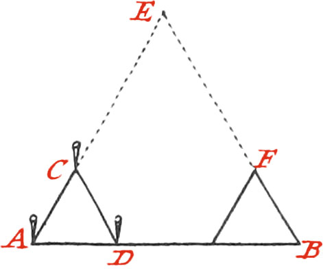
Use XI. To find the Distance of two Objects, inaccessible in respect of each other.
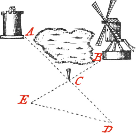
The Distance, for Example, from the Tower A, to the Windmill B, is required.
Plant the Staff C in some Place from whence it may be easy to measure the Distance in a right Line from it to the Places A and B.
Measure these Distances exactly, as for Example, from C to A, which suppose 54 Toises; then produce the Line AC to D, likewise 54 Toises: measure also the Line BC, which suppose 37 Toises, and produce it to E, so that CE may be 37 Toises likewise; by which means the Triangle CDE, will be formed equal and similar to the Triangle ABC, and consequently the Distance DE will be equal to the proposed inaccessible Distance from B to A.
Use XII. To find the Distance of two Objects, one of which is in accessible.
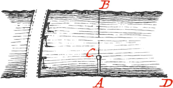
Let it be proposed, for Example, to find the Breadth AB of a River: being at one of it’s Sides A, plant there a Staff AC, 4 or 5 Feet high, and very upright; make a Slit towards the Top of the Staff, in which put a very straight Piece of Steel or Brass (that may slide up and down), about 3 Inches long, which must be slipped up or down, ’till the Point B, on the other Side of the River be seen along it; afterwards turn the Staff, and look along (keeping the aforesaid Piece of Brass in the same Position) the Side of the River upon level Ground, ’till you see the Point D, where the visual Rays terminate. The Distance AD measured with a Chain, will give the Breadth of the River, to which it is equal.
This Proposition, as simple as it is, may serve to know what Length Timber must be of, to make Bridges over Ditches or Rivers.
Use XIII. To find the Distance of two Objects, one of which is in accessible.
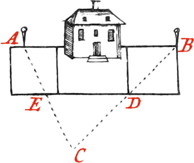
Find, upon very level Ground, a third Point, as C, from which you may see Staffs planted in the Points A and B; then measure exactly the Distance from C to A, and from C to B: this being done, take the Half, Third, or any other Part of each of those Lines, whereat plant Staffs, as in D bisecting CB, and in E bisecting CA; then draw a right Line from D to E, which produce as is necessary, and draw a Parallel to it passing by the Points A and B, by means of Staffs planted between the Point A and the House, as also between the House and the Point B, which will shew the Direction from A to B.
Use XIV. It is required to cut a Passage thro’ a Hill from the Point A to B.
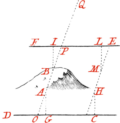
Draw on one Side of the Hill a right Line, as DC, and on the other Side another right Line, as EF, parallel to CD; then let fall from the Point A, to the Line CD, the Perpendicular AG; and in some other Point beyond the Hill, draw another Perpendicular, as CH, equal to AG.
Again; from the Point B, let fall upon the Line EF the Perpendicular BI; and from some other Point beyond the Hill, draw another Perpendicular to the same Line, as LM, equal to BI, so that the Distance IL, may be equal to CG; then draw a right Line from the Staff H, to the Staff M (and produce it as far as is necessary), which will be parallel to the Passage to be made from A to B; therefore any Number of Staffs may be planted at an equal Distance to that Parallel HM on both Sides the Hill, as O, P, Q, which will serve as a Guide to pierce the Hill thro’ from A to B.
I shall again mention the Use of the aforesaid Instruments, in the little Treatise of Fortification, hereafter laid down.