Of the Description and Use of the Surveying-Cross.
Fig. 15
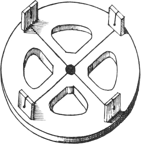
The Surveying-Cross is a Brass Circle of a good Thickness, and 4, 5, or 6 Inches Diameter. It is divided into 4 equal Parts, by two Lines cutting one another at right Angles in the Center. At the four Ends of these Lines, and in the Middle of the Limb, there are fixed four strong Sights well riveted in square Holes, and very perpendicularly slit over the aforesaid Lines, having Holes below each Slit, for better discovering of distant Objects: the Circle is hollowed to render it more light.
Fig. 16
Underneath, and at the Center of the Instrument, there ought to be screwed on a Ferrel, serving to sustain the Cross upon it’s Staff of 4 or 5 Feet long, according to the Height of the Observer’s Eye. This Staff must be furnished with an Iron Point, to go into the Ground the better.
All the Exactness of this Instrument consists in having it’s Sights well slit at right Angles, which may be known by looking at an Object thro’ two Sights, and another Object thro’ two other Sights: then the Cross must be exactly turned upon it’s Staff, and you must look at the same Objects through the opposite Sights; if they are very exactly in the Direction of the Slits, it is a sign the Instrument is very just.
To avoid breaking or damaging the Cross, the Staff must first be put in the Ground, and when it is well fixed, the Cross must be screwed upon it.
These kinds of Crosses sometimes are made with eight Sights, in the same manner as the aforesaid one, and serve to take Angles of 45 Degrees; as also for Gardeners to plant Rows of Trees by.
Use I.To take the Plot and Area of a Field within it.
Fig. 17
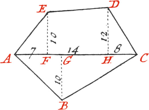
Let the Field proposed be ABCDE, and having placed at all the Angles Staffs, or Poles very upright, exactly measure the Line AC (in the manner we have already laid down, or any other at pleasure) then make a Memorial, or rough Draught, somewhat representing the Field proposed, on which write all the Dimensions of the Parts of the Line AC, and of Perpendiculars drawn from the Angles to the Line AC. If, for Example, you begin from the Staff A, find the Point F in the Line AC, upon which the Perpendicular EF falls: then measure the Lines AF and EF, and set down their Lengths upon their correspondent Lines in your Memorial.
Now to find the Point F, plant several Staffs at pleasure in the Line AC; as also the Foot of your Cross in the same Line, in such a manner that you may discover thro’ two opposite Sights, two of those Staffs, and thro’ the other two Sights (which make right Angles with the two first ones), you may see the Staff E. But if in this Station the Staff E cannot be seen, remove the Instrument backwards or forwards, ’till the Lines AF, EF, make a right Angle in the Point F, by which means the Plot of the Triangle AFE will be had.
In the same manner may the Point H be found, where the Perpendicular DH falls, whose Length, together with that of GF, must be set down in your Memorial, in order to have the Plot of the Trapezium EFHD. Again, Measure HC making a right Angle with HD, and the Plot of the Triangle DHC will be had.
Having likewise measured the whole Line AC, there is no more to do but find the Point G, where the Perpendicular BG falls; and proceeding as before, the Plot of the Triangle ABC may be had, and consequently the Plot of the whole Field ABCDE. The Area of the Field will likewise be had, by adding the Triangles and Trapeziums together, which may easily be done by the Rules of Planometry, in the following manner:
Suppose, for Example, AF to be 7 Toises, and the Perpendicular EF 10; multiply 7 by 10, and the Product is 70, half of which is 35, the Area of the Triangle AFE.
If moreover the Line FH be 14 Toises, and the Perpendicular HD 12, add 12 to 10 (which is the Perpendicular FE), the Sum will be 22, half of which being 11, multiplied by 14, will give 154 square Toises, for the Area of the Trapezium EFHD; and if the Line HC is 8 Toises, multiplying 8 by 12, the Product is 96, whose half 48, will be the Area of the Triangle CHD.
The whole Line AC is 29 Toises, and the Perpendicular BG 10; whence the Product: is 290, whose half 145, is the Area of the Triangle ABC. Finally, adding together 35, 154, 48, and 145, the Sum 382, will be the Number of square Toises contained in the Field ABCDE.
Use II.To take the Plane of a Wood, morass, &c. in which it is not easy to enter.
Fig. 18
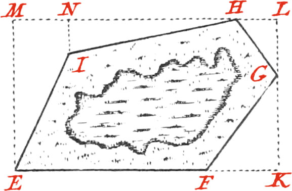
Let the Morass EFGHI be proposed: Set up Staves at all the Angles, so made as to include the Morass within a Rectangle, which measure; then substract the Triangles and Trapezia included between the Sides of the Morass, and the Sides of the Rectangle, from the said Rectangle, and the Area of the proposed Morass will be had.
If, for Example, you begin at the Staff E, produce by help of the Cross the Line EF, as far as is necessary, to which, from the Point G, let fall the Perpendicular GK; set up a Staff at K, and produce KG to L, to which, from the Point H, draw the Perpendicular LH, which likewise produce as far as is necessary: afterwards draw from the Staff E, to the Line HL, produced, the Perpendicular EM: whence the Rectangle EMLK will be had, whose Sides must be measured with a Chain or Toise.
Suppose, for Example, the Line EK, or it's Parallel ML (which ought to be equal to it) is 25 Toises, and the Line EM, or it’s Parallel, 10 Toises; multiplying these two Numbers by one another, there will arise 350 square Toises for the Area of the Rectangle EMLK: but if FK be 5 Toises, and GK 4, by multiplying 4 by 5, the Product is 20, whose half 10 Toises, is the Area of the Triangle FKG. The Line GL, being 6 Toises, and HL 4, the Product of 4 by 6 is 24, whose half 12 is the Area of the Triangle GLH,
Afterwards a Point must be found in the Line HM, where a Perpendicular drawn from the Staff 1 falls, which forms a Triangle and a Trapezium; so that if the Distance HN be 24 Toises, and the Perpendicular NI 4 Toises, 24 by 4 gives 96, whose half 48, is the Area of the Triangle HNI. Lastly, NM being 7 Toises, ME 10, and it's Parallel NI 4 Toises, adding 10 to 4, the Sum will be 14, whose half 7, multiplied by 7, produces 49 for the Area of the Trapezium EMNI.
Therefore adding together the Areas of the three Triangles, and that of the Trapezium, there will be had 119 Toises, which taken from 350, the Area of the Rectangle, and there remains 231, the Area of the proposed Morass. The same may be done with any other Figure. These two Uses are enough to shew how Surveyors use their Instruments for measuring and taking the Plot of any Piece of Ground.