Mathematical Instruments
Book IV. Ch. III.

Of the Construction and Uses of divers Instruments to take Angles.

There are several Sorts of Instruments to take Angles, but the best and most in use, are those whose Description we are now going to give.

Fig. A

The Instrument A, is composed of two Rules very equal in breadth, for the Insides of them must be parallel to their Outsides; their Breadth is about an Inch, and their Length a Foot or more. Those two Rulers are equally rounded at the Top, and fastened to one another by means of a Rivet artificially turned, so that the Instrument may easily open and shut. When an Angle is taken with it, the Center of a Protractor must be put to the Place where the two Rulers join each other, and the Degrees cut by the Edge, will show the Quantity of the Angle; or else the Angle which the two Rulers make, is drawn upon Paper, and then it is measured with a Protractor.

Fig. B

The Instrument B, is made like the precedent one, only there are two Steel Points at the Ends, in order for it to serve as a Pair of Compasses.

Fig. C

The Instrument C, is different from the others, because it shews the Quantities of Angles without a Protractor.

It is composed of 2 Brass Rulers of equal Breadth and parallel, about 2 Feet long, and 2 or 3 Inches thick, joined together by a very round Rivet: it has besides a Circle divided into 360 Degrees at the End of one of the Rulers, and a little Index fixed to the Rivet, which shews the Number of Degrees the 2 Rulers contain between them. I shall not here shew how to divide the Circle, having sufficiently spoken of it in the Construction of the Protractor; only note, that the Degrees are always reckoned from the Middle of the Rule, where the Center is.

There are these Sorts of Instruments made by dividing a Circle upon the under Ruler, and filing the upper one like the Head of a Sector, that thereby the Degrees of the Opening of the Legs may be known, by means of the two Shoulders of the upper Leg.

To measure a saliant Angle with any one of the three Recipient-Angles, apply the Insides of the two Rulers, to the Lines forming the Angle; and to measure a rentrant Angle, apply the Outsides of the same Rulers to the Lines forming the Angle.

Fig. D

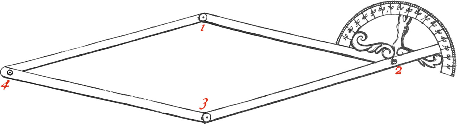
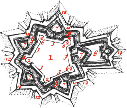
The Instrument D, is made of 4 Brass Rules, equal in Breadth, joined together by 4 round Rivets, forming an equilateral Parallelogram.

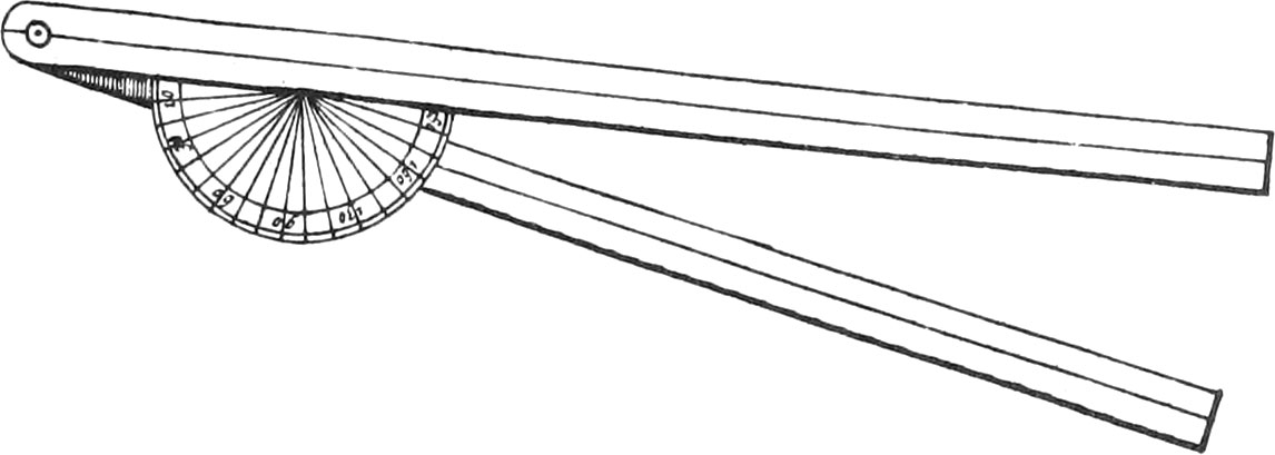
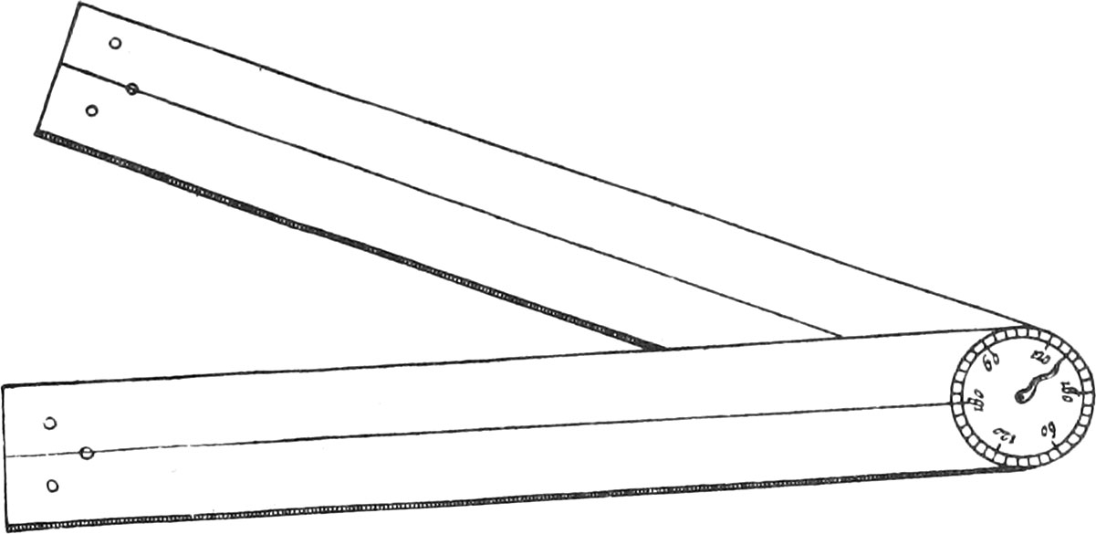
At the End of one of the Rules there is a Semi-circle, divided into 180 Degrees. The other Branch passing upon the Semi-circle, is continued to the Divisions of the Semi-circle, in order to shew the Quantities of Angles.

The said Rules are made one or two Feet long, 8 or 10 Lines broad, and of a convenient Thickness; they ought to be drilled very equal in Length, namely, that where the Center of the Semi-circle is (marked 2.) and at the other End in the Point 1. That which serves for an Index, ought to be drilled in the Points 2 and 3. And lastly, The two other Rules in the Point 4. The Rule serving for an Index, must be fastened to the Center of the Semi-circle; and the two other Rules, which are of equal Length, must be fastened underneath the two others, all of them so as their Motion may be very uniform.

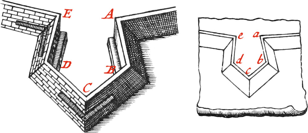
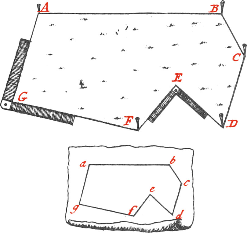
When a saliant Angle is to be measured with this Instrument, the 2 equal Rules must be put underneath the 2 others, so that the End 4 be underneath 2, and thereby the 4 Rules make but 2 to encompass the Angle: but when a rentrant Angle is to be measured, the two Rules must be drawn out (as per Figure), and applied to the Corner of the Angle; and since in every Parallelogram the opposite Angles are equal, the Degrees of the Angle may be known by the Semi-circle.

Use I. Of the Recipient-Angle.

Fig. 19

To take the Plan of a Bastion; as, for Example; ABCDE, make a Memorial, and then measure, with the Instrument, the rentrant Angle E, made by the Courtine of the Place, and the flanquant Angle of the proposed Bastion, by applying it horizontally, in such manner that one of the Rules may be in the Direction of the said Courtine, and the other in the Direction of the Flank; and having found the Quantity of it in Degrees, set it down upon a little Arc in your Memorial; then measure the Flank ED, which set down upon the Line ed in your Memorial. Again, apply the Rules of your Instrument to the saliant Angle D, and set down it's Quantity upon a little Arc; measure the Length of the left Face CD, take the Quantity of the flanquant Angle C, and of all the other Angles of the Bastion, as likewise the Length of the Faces and Flanks; after which, by help of a Scale, the Plan of the Bastion may be drawn neat.

But since it often happens that these Angles, which are commonly made of Free-Stone, are not well cut, by the Negligence of Workmen, who make them either too acute or obtuse; to remedy this, there must be a long Rule horizontally applied to each Wall, whose Direction is good, tho’ the Angles are not; and putting the Legs of the Instrument level upon those two Rules, the Angle to be measured may be more exactly had.

Use II. To take the Plot of a Piece of Ground encompassed by right Lines.

Fig. 20

Let the Piece of Ground proposed be ABCDEFG; measure exactly the Length of all the Sides, and set them down upon the relative Lines of your Memorial; then take, with any recipient Angle, the Quantity of each Angle, as, for Example, the Angle AGF, and set down the Quantity of it upon the relative Angle agf, in the Memorial; measure also the Angle FED, by applying the Instrument to it (as per Figure), and set down the Quantity thereof upon the relative Angle of the Memorial, and so of all the other Angles, whose Quantities being noted in Degrees, as likewise the Lengths of all the Lines, the Plot abedefg may be neat drawn, and similar to ABCDEFG.

Fig. Pentagon fortified

In this Plate may be seen the Plane of a Pentagon fortified, with the Names of the Parts of it’s Fortification.

  1. A Pentagon Fortify’d
  2. Bastions
  3. Courtains
  4. the Faces
  5. the Flanks
  6. the Gorge
  7. Ravelins
  8. a Horn work
  9. the Ditch
  10. the Covertway
  11. Palisades
  12. the Glacis
  1. Previous Book IV. Chapter II. Surveying-Cross
  2. Contents
  3. Next Book IV. Chapter IV. Theodolite