This Instrument is made of Wood, Brass, or any other solid Matter, commonly circular and about one Foot in Diameter. In the Center of this Instrument is set upright a little Brass Cylinder, or Pivot, about which an Index turns, furnished with two Sights, or a Telescope, having a right Line, called The Fiducial Line, exactly answering to the Center of the aforesaid little Cylinder, whose Top ought to be cut into a Screw, for receiving a Nut to fasten the Index, upon which is fixed a small Compass for finding the Meridian Line.
The Limb of the Theodolite is a Circle of such a Thickness, as to contain about six round Pieces of Pasteboard within it (of which we are going to speak), and of such a Breadth as to receive the Divisions of 360 Degrees, and sometimes of every fifth Minute.
There are several round Pieces of Pasteboard, of the Bigness of the Theodolite, pierced thro’ the Middle with a round Hole, exactly to fit the Pivot; so that the Pivot may be put thro’ each of the aforesaid Holes in the Pieces of Pasteboard, and the upper Pasteboard may have the Index moving upon it. This upper Pasteboard may be fixed at pleasure, by means of a little Point fastened to the Limb of the Instrument, and entering a little way into the Pasteboard. There is commonly drawn with Ink, upon each of these Pasteboards, a Radius or Semidiameter, serving for a Station-Line.
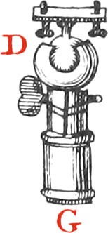
Figs. D & G
Underneath the Theodolite is fastened a Ball and Socket, represented by the Figure D, which is a Brass Ball enclosed between two Shells of the same Metal, that may be more or less opened by means of a Screw, and a Socket G, in which goes the Head of a three-legged Staff; of which more by and by.
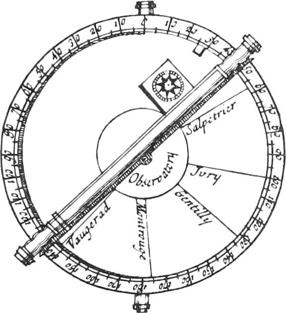
Fig. A, represents the Instrument put together. We now proceed to shew the Construction of the Pieces composing it, in beginning with the Division of it’s Limb.
First, Draw upon the Limb two or three concentrick Circles, to contain the Degrees, and the Numbers set at every tenth Degree; then divide one of these Circumferences into four very equal Parts, each of which will be 90 Degrees; and dividing each of these four Parts into 9 more, the Circumference will be divided into every tenth Degree. Again, each of these last Parts being divided by 2, and each of those arising into 5 equal Parts, the whole Circumference will be divided into 360 Degrees. This being done, you must draw the Lines of these Divisions upon their convenient Arcs, by means of a Ruler moving about the Center. Afterwards Numbers must be set to every tenth Degree, beginning from the Fiducial Line, which is that whereon the two fixed Sights or Telescope is fastened.
A Theodolite thus divided is of much greater Use than those whose Limbs are not divided; for it may serve exactly to take the Plots of Places, and measure inaccessible Distances by Trigonometry.
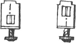
Fig. B
The Figures B represent the Sights which are placed upon different Instruments; that to which is placed the Eye, hath a long strait Slit, which ought to be very perpendicular, made with a fine Saw; and that which is turned towards the Object, hath a square Hole, so large, that the adjacent Parts of a distant Object may be perceived thro’ it: And along the Middle of this Hole is drained a very fine Gut, in order to vertically cut Objects, when they are perceived thro’ the Slit of the other Sight. But that the Eye may be indifferently placed at any one of the two Sights at pleasure, so that Objects may be as well perceived thro’ the Sights on one Side the Instrument, on which they are placed, as on the other; there is made in each Sight a square Hole and a Slit, the Hole in one Sight being below the Slit, and in the other Sight above it, as the little Figures shew. These Sights ought to be exactly placed on the Extremes, and in the fiducial Line, as well of Instruments as Indexes, and are fastened in little square Holes with Nuts underneath, or else by means of Screws, according as the Place they are fastened on requires.
Fig. C
The little Figure C represents the aforesaid Cylinder, or Pivot, with it’s Nut, for joining the Index to the Theodolite; those of Semicircles, and other Instruments, are made in the same manner, only they are rivetted underneath.
Figs. D & G
The Figure D represents the Ball and Socket for supporting the Instrument, and is composed of a Brass Ball inclosed between two Shells of the same Metal, which are made very round, with Balls of tempered Steel cut in manner of a File. These Shells are locked more or less by means of a Screw, that so they may press the Ball inclosed between them according to necessity. One of these Shells is soldered to the Socket G, which is a turned Brass Ferrel, in which the Foot of the Instrument is put. Balls and Sockets are made of different Bignesses, according to the Bignesses of Instruments, and are fastened to the Instruments with Screws, in a Plate riveted to the Top of the Ball.
Construction of the Feet for Supporting of Instruments.
We have already mentioned the simple Feet for supporting Surveying-Crosses, which are to be forced into the Ground; but those whose Description we are now going to give, are not to be forced into the Ground, but are opened or shut according as the Inequality of the Ground, the Instrument is to be used upon, requires.
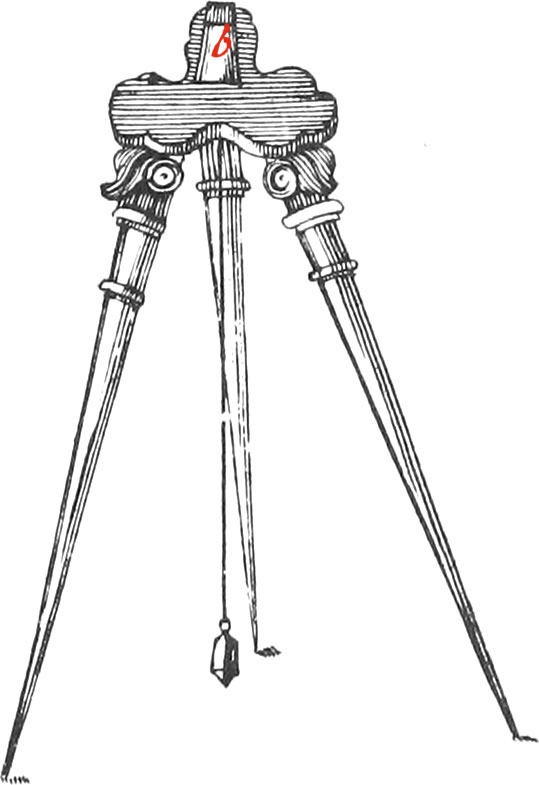
Fig. E
The Foot E is a triangular Plate, in whose Middle is a Piece b, which is to go into the Socket G.
Underneath the aforesaid Plate are fastened three Ferrels, or Sockets, moveable by means of Joints, for receiving three round Staves of such a Length, that the Observer’s Eye, when the Instrument is using, may commodiously view Objects thro’ the Telescope, or Sights. The Extremities of these Staves are furnished with Ferrels and Iron Points, in order to keep the Instrument firm when it is using.
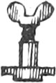
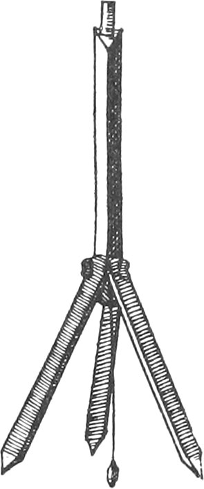
Fig. F
The Foot F consists of four Staves, about two Foot long, whereof that in the Middle, called the Shank, hath it’s Top rounded, that so it may go into the Socket; the rest of this Staff is cut in Figure of a Triangle, that so the three Faces thereof may receive upon them three other Staves, fastened by means of three Screws (all of a piece) and so many Nuts. These three Staves are furnished with Ferrels and Iron Points, being flat within side, and have three Faces without.
When we have a mind to carry this Foot, we re-unite all the Staves together, so that they make, as it were, but one, and by this means are shorter by about the half, than when the Foot is using.
We generally hang to the Middle of each of these Feet a Thread and Plummet, in order to know the Station-Point.
Use of the Theodolite.
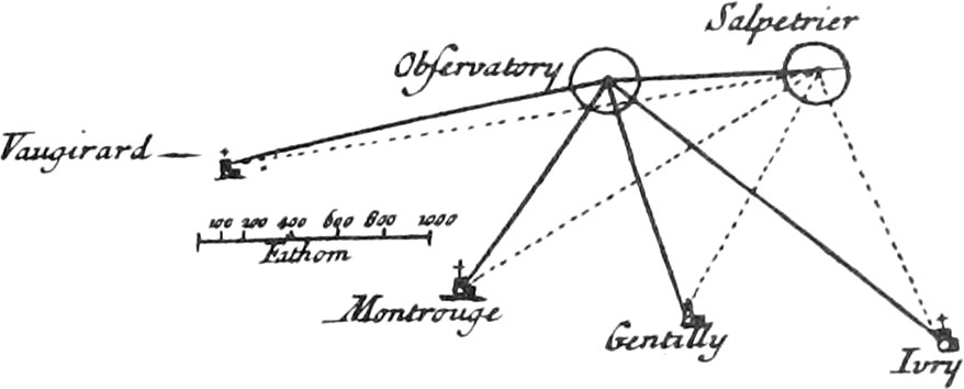
Fig. 1
To take the Map of a Country by this Instrument, chuse two high Places, for Example, the Observatory, and the Salt-Petre House, from whence the Country nigh Paris, a Map of which is to be made, may be seen; then mark round the Center of the upper Pasteboard the Name of the Place chosen for the first Station, and having fixed it by means of the Point on the Limb of the Theodolite, put the Index upon it, which sufficiently screw down by means of the Nut and Screw.
Now having placed the Theodolite upon it’s Foot, planted at the Observatory, and given it a Situation nearly horizontal, so that it may remain steddy while the Index is moving, observe thro’ the Sights the Steeple of the Salt-Petre House, and along the fiducial Line of the Index from the Center draw the Station-Line.
Then turn the Index, and observe some remarkable Object thro’ the Sights, as the Steeple of Vaugirard, towards which a Line must be drawn upon the Pasteboard, from the Center, along the fiducial Line of the Index, and along this Line write the Name of the Place viewed thro’ the Sights.
Again, direct the Index towards some other Object (as Mont-rouge) and draw a Line towards it from the Center, along the fiducial Line, and upon this Line write the Name of the Place observed. Proceed in the same Manner with all the considerable Places that can be seen from the Observatory.
Now having removed the Theodolite from it’s first Station, having well observed it’s Place, and transported it to some other designed Place, as to the Salt-Petre House; measure the exact Distance between the two Stations upon level Ground, the Number of Toises of which must be set down upon your Pasteboard, which must now be turned, or taken from under the Index, that so at every different Station, the upper Face of the Pasteboard, upon which the Index is, may be clean: then set down about the Center of this new Pasteboard, the Name of the Place of your second Station, and upon the Base Line the Number of Toises measured, that so you may remember this Line is the same as that on the precedent Pasteboard. The Theodolite being placed here, dispose it so, that placing the fiducial Line of the Index upon the Station Line, you may discover thro’ the Sights, the Observatory, which was your first Station.
The Instrument remaining firm in this Situation, turn the Index, and successively. view thro’ the Sights the former Objects observed from the Observatory, and draw Lines, as before, upon the Pasteboard, along the Index, from the Center towards the Places viewed, and upon each Line write the correspondent Name of the Place.
If all the Places you have a mind to set down in your Map, cannot be seen from the two precedent Stations, you must chuse a third Place from whence they may be observed, and make as many new Stations, as are necessary for perceiving each remarkable Object, from two Places sufficiently distant from each other.
Now to represent this Map upon a Sheet of Paper, first draw a right Line at pleasure upon it, for a common Base, which divide into the same Number of equal Parts, as you have measured Toises upon the Ground. About one End of this Line, as a Center, describe circular Arcs equal to those drawn upon the first Pasteboard, and upon the other Extreme, Arcs equal to those drawn upon the second Pasteboard, and produce the Lines forming the Arcs ’till they meet each other; then the Points of Concourse, will be the Points of Position of the Places observed.
The aforesaid Places may be laid down upon the Paper easier, by placing the Centers of the Pasteboards upon the Extremities of the common Base, and noting upon the Paper the Ends of the Lines drawn upon the Pasteboard, and then drawing Lines from the Stations thro’ those Points ’till they intersect.
By means of this Theodolite may be had in Degrees, or Parts, all the Angles that the Places viewed thro’ the Sights or Telescopes, make, with the Places whereat the Instrument is placed.
What we have said, is sufficient to shew the Manner of using the Theodolite in taking the Position of Places, and making of Maps, because the Operations are the same for all different Places; but for it’s Uses, with regard to Trigonometry, they are the same as those of the Semi-circle and Quadrant, of which we are going to treat.