Of the Construction and Uses of the Quadrant, and Geometrick Quadrat.
Fig. G
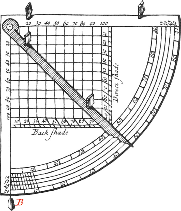
The Figure G, represents a Quadrant and Geometrick Square, with it’s Index and Sights.
It is commonly made of Brass, or other solid Matter, 12 or 15 Inches Radius, and an answerable Thickness. It’s Circumference is first divided into 90 Degrees, and every Degree into as many equal Parts as possible, without Confusion, and in such manner, that the Divisions and Subdivisions may be just, and very distinctly marked upon the Limb of the Instrument.
To do which, there must first be 2 Arcs drawn nigh the Edge of the Quadrant, about 8 or 9 Lines distant from each other; and after having divided them into Degrees, draw Diagonal Lines between them, from the first Degree to the second, from the second to the third, and so on to the last.
After which, if you have a mind to subdivide every Degree into 10 Minutes, there must 5 Other concentrick Arcs be described from the Center of the Instrument, cutting all the aforesaid Diagonals; but if every Degree is to be subdivided into Minutes, there must be 9 concentrick Arcs described between those two first drawn.
The Distances between all these Arcs, must not be all equal, because the Extent of a Degree taken in the Breadth of the Limb, forms a kind of Trapezium, broader towards the outward Arc, and narrower towards the inward one; whence a mean Arc dividing every Degree into 2 equal Parts, must be nigher the inward Arc than the outward one, and the others in proportion.
Fig. H
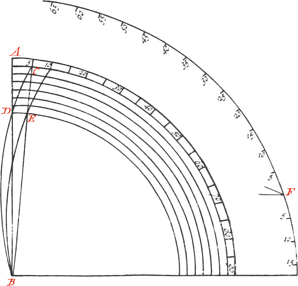
To make these Subdivisions exactly, the Diagonals must be Curve Lines, as BDC, described in making the Portion of a circular Arc pass thro’ the Center B, the beginning of the 1st Degree marked D, upon the inward Arc, and the End C of the same Degree, on the outward Arc: which is easy to do by Use 18. Lib. 1. which shews how to make a Circle pass thro’ 3 Points given, by which means the Point F, the Center of the Diagonal Curve, passing thro’ the first Degree, will be found.
Afterwards one of these Diagonal Curves must be divided into equal Parts, and from the Center of the Instrument, there must be drawn as many concentrick Arcs, as each Degree is to have equal Parts.
The Reason of this Operation is, that the Diagonal Curve being divided into equal Parts, if from the Center of the Instrument there are drawn right Lines thro’ all the Points of Division of that Arc, there will be had (per Prop. 27. Lib. 3. Eucl.) as many equal Angles in the Center, because they will be all in the Circumference of the same Circle, and stand upon equal Arcs.
But since it is troublesome to find the Centers of 90 Arcs, each passing thro’ 3 Points; and since it is manifest, that all the Centers of these Arcs ought to be placed in the Circumference of a Circle whose Center is the Point B; there is no more to do but draw a Circle from the Center B, with the Distance BF, and divide it’s Circumference into 360 equal Parts; upon every of which, setting one Foot of your Compasses, you may describe with the same Extent FB, all the Arcs between the Circles AC, DE, and then the circular Arcs; which are Diagonals, will likewise divide the Circumferences, upon the Limb of the Instrument, into Degrees. Note, Because the Figure is too little, it is divided but into every 5th Degree.
Diagonal Curves may also be drawn without transferring the Foot of your Compasses from one Degree to another, upon the aforesaid Arc, in fixing the Foot of your Compasses in only one Point, as F, and letting the Instrument be gradually turned about the Center of a large Circle, whose Limb is already divided into Degrees, by means of a Rule strongly fastened upon the Instrument, and reaching to the Divisions of the large Circle.
Ingenious Workmen may shorten their Work by adjusting a fine Steel Ruler, according to the Curvature of the first Diagonal, which being drawn, by this means they may draw all the others. If Diagonal right Lines are to be drawn from one Degree to the other, the Lengths of the Radii of each of the Circumferences cutting the Diagonals, may be found by Trigonometry, an Example of which is as follows:
Suppose a Quadrant be 6 Inches Radius, which is the smallest accustomed to be divided by Diagonals. Suppose also you have a Scale of 1000 equal Parts, and that the Distance from the inward Arc to the outward one, is 9 Lines, answering to 125 of such Parts, whereof the Radius is 1000; whence, by Calculation, I find that the right-lined Diagonal, drawn from one Degree to that which follows it, is 126 of the same Parts; and that the Radius of the inward Arc, which is 5 Inches, 3 Lines, contains 875 of them.
The obtuse Angle made by the Radius and the Diagonal, is 172 Deg. 2 Min. and afterwards calculating the Lengths of the Radii of the Circumferences cutting the Diagonals, and dividing them into every 10 Minutes, I find that the Radius of 10 Min. is 894 of the same equal Parts, instead of 896 which it would have contained, if the Distance between the inward and outward Arc had been divided into 6 equal Parts. The Radius of 20 Minutes ought to contain 913 of them, instead of 917; the Radius of 30 Minutes ought to contain 933 of them, instead of 938; the Radius of 40 Minutes ought to contain 954 of them, instead of 959. Lastly, the Radius of 50 Minutes ought to contain 977, instead of 980, which it must, if the aforesaid Distance be divided into 6 equal Parts.
The greatest Error, which is about 5 Parts, answers to about \(\frac{1}{8}\) of a Line, which may cause an Error of 2 Minutes; but this Error diminishes in proportion as the Radius of the Quadrant augments in respect of the Diagonals, so that the Error will be less by half, if the Radius of the Quadrant be one Foot, and the Distance of the inward and outward Arcs is but 9 Lines.
What we have said as to the Divisions of the Quadrant, may likewise be applied to Theodolites, Circles, Semi-circles, or any other Portions of Circles to be divided into Minutes.
As to the Geometrick Square, each Side of it is divided into 100 equal Parts, beginning at the Ends, that so the Number 100 may end at the Angle of 45 Degrees. These Divisions are distinguished by little Lines from 5 to 5, and by Numbers from 10 to 10; all those Divisions being produced from a kind of Lattice, both ways containing 10000 small and equal Squares.
This Quadrant is furnished with two immoveable Sights, fastened to one of it's Semi-diameters, and with a Thread and Plummet fixed to the Center, as likewise a moveable Index, with two other Sights, fastened to the Center, with a Headed-Rivet. The Sights are nearly like those belonging to the Theodolite.
Instead of immoveable Sights, there is sometimes fastened to one of the Radius’s of the Quadrant a Telescope, and then the 1st Point of Division of the Circumference may be found in the manner as is explained hereafter in the Astronomical Quadrant: for this Quadrant is designed only to take the Heights and Distances of Places on Earth.
Upon the under Surface of this Quadrant, is a Ball and Socket fastened with 3 Screws, by means of which it may be put into any Position fit for Use.
This Instrument may be put in Use in different Situations; for first, it may be so disposed that it’s Plane may be at right Angles with the Horizon, for observing Heights and Depths, which may yet be done two different ways, viz. in using the fixed Sights, and the Thread and Plummet, and then neither of it’s Sides will be found parallel to the Horizon; or else by keeping the Sights fastened to the Index moveable, and then one of the Semi-diameters of the Quadrant will always be parallel to the Horizon, and the other perpendicular: which may be done by means of a Plummet suspended in the Center, and then the fixed Sights are useless.
Finally, the Quadrant may be placed so as it’s Plane may be parallel to the Horizon, for observing horizontal Distances with the Index and immoveable Sights, and then the Thread, with it's Plummet, is not in use.
Uses of the Quadrant, with two fixed Sights and a Plummet.
Use I.To take the Height or Depth of any Object in Degrees.
As suppose the Height of a Star or Tower is to be taken in Degrees; place the Quadrant vertically, then place your Eye under that fixed Sight next the Circumference of the Quadrant, and direct it so, that the visual Rays passing through the Holes of the Sights, may tend to the Point of the Object proposed (as to the Sun, it is sufficient that it’s Rays pass thro’ the aforesaid Holes): then the Arc of the Circumference contained between the Thread and it’s Plummet, and the Semi-diameter on which the Sights are fastened, will show the Complement of the Star’s Height above the Horizon, or it’s Distance from the Zenith: Whence the Arc contained between the Thread, and the other Semi-diameter towards the Object, shews it’s Height above the Horizon. The same Arc likewise determines the Quantity of the Angle made by the visual Ray, and a horizontal Line, parallel to the Base of the Tower.
But to observe Depths, as those of Wells or Ditches, the Eye must be placed over that Sight, which is next the Center of the Quadrant.
The whole Operation consists in calculating Triangles by the Rule of Three, formed in the Proportion of the Sines of Angles, to the Sines of their opposite Sides, according to the Rules of right-lined Trigonometry, of which we are now going to give some Examples.
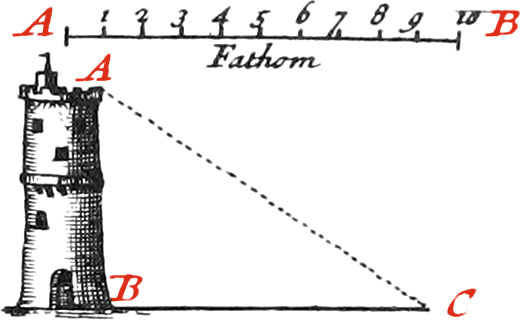
Use II.Let it be required to find the Height of the tower AB, whose Base is accessible.
Fig. 2
Having planted the Foot of your Instrument in the Point C, look at the Top of the Tower thro’ the fixed Sights; then the Thread of the Plummet freely playing, will fix itself upon the Number of Degrees, determining the Quantity of the Angle made at the Center of the Quadrant, by the visual Ray, and the horizontal Line, parallel to the Base of the Tower, accounting the Degrees contained between the Thread and the Semi-diameter next to the Tower.
Now suppose the Thread fixes upon 35 Deg. 35 Min. and having exactly measured the level Distance from the Foot of the Tower, with a Chain, to the Place of Observation, you will find it 47 Feet; then there will be 3 things given, to wit, the Side BC, and the Angles of the Triangle ABC: for since Walls are always supposed to be built upright, the Angle B is a right Angle, or 90 Deg. and consequently the 2 acute Angles A and C, are together equal to 90 Degrees, because the three Angles of any right-lined Triangle, are equal to 180 Degrees, or 2 right Angles.
Now the Angle observed, is 35 Deg. 35 Min. whence the Angle A is 54 Deg. 25 Min. therefore you may form this Analogy, As the Sine of 54 Deg. 25 Min. is to 47 Feet, So is the Sine of 35 Deg. 35 Min. to a fourth Term, which will be found 33\(\frac{1}{2}\) Feet, to which adding 5 Feet, the Height of the Observer’s Eye, and the Height of the proposed Tower will be found 38\(\frac{1}{2}\) Feet.
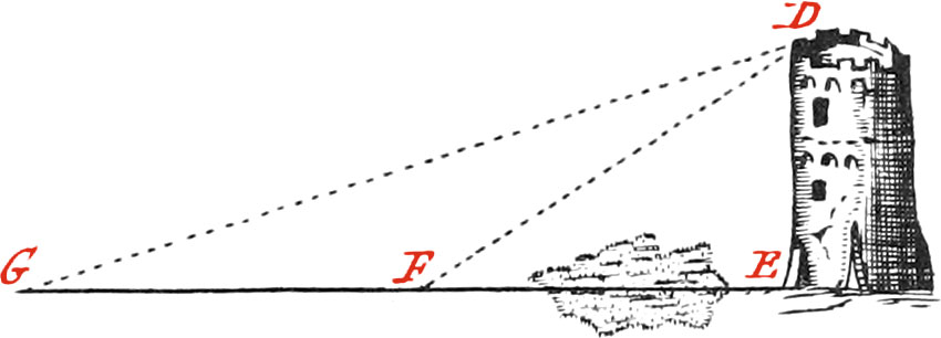
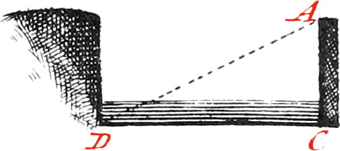
Use III.Let it be required to find the Height of the inaccessible Tower DE.
Fig. 3
In this Case two Observations must be made, as follow:
Place the Foot of your Quadrant in the Point F, and look thro’ the two immoveable Sights to the Top of the Tower D; then see on what Degree the Thread of the Plummet fixes, which suppose on the 34th. This being done, remove the Instrument, planting a Staff in it’s Place, and set it up in some other Place level to the Place it was in before, as in the Point G, in the same right Line, and look thro’ the aforementioned Sights, at the Point D of the Tower. Note the Point in the Limb of the Quadrant that the Thread cuts, which suppose 20 Degrees. Measure likewise very exactly, the Distance between the two Stations, which suppose 9 Toises, or 54 Feet.
This being done, all the Angles of the Triangle DFG will be known, as also the Side FG measured; by which means it will be easy to find the Side DF, and afterwards the Side ED, by making the following Analogies.
The Angle EFD being found 34 Deg. it’s Complement DFG to 180 Deg. will be 146 Deg. and the Angle G having been found 20 Deg. it follows that the Angle FDG is 14 Deg. therefore say, As the Sine of 14 Deg. is to 54 Feet, So is the Sine of 20 Deg. to a fourth Term, which will be 76 Feet, and about \(\frac{1}{3}\), for the Side DF: then say, As Radius is to the Hypothenuse FD, So is the Sine of the Angle DFE, to the Side ED, which will be found 42\(\frac{2}{3}\) Feet; to which adding 5 Feet, the Height of the Center of the Instrument above the Ground, and there will be had 47\(\frac{2}{3}\) Feet, for the Height of the Tower proposed.
These Calculations are much better made with Logarithms, than by common Numbers, because they may be done by only the help of Addition and Substraction, as is more fully explained in Books of Trigonometry.
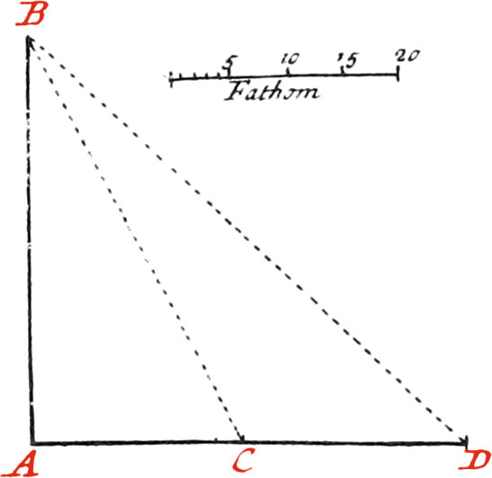
These Propositions, and others the like, may be also geometrically solved, by making Triangles similar to those formed upon the Ground.
As to solve the present Question, make a Scale of 10 Toises, that is, draw the right Line AB so long, that the Division of it may be exact; and then divide it into 10 equal Parts, and subdivide one of these Parts into 6 more, to have a Toise divided into Feet.
Then draw the indeterminate Line EG, and make with a Line of Chords, or Protractor, an Angle at the Point G of 20 Degrees, and draw the indeterminate Line GD. Lay off 9 Toises, or 54 Feet, from G to F; then make at the Point F an Angle of 34 Degrees, and draw the Line FD, cutting the Line GD in some Point as D, from which let fall the Perpendicular DE, which will represent the Height of the proposed Tower, and measuring it with the Scale, you will find it to contain 47 Feet, 8 Inches. All the other Sides of these Triangles may likewise be measured with the same Scale.
Use IV.To find the Breadth of a Ditch, or Well, whose Depth may be measured.
Fig. 4
Let it be proposed to measure the Breadth of the Ditch CD, which may be approached.
Place the Quadrant upon the Brink in the Point A, so that you may see thro’ the Sights the Bottom of the Ditch, at the Point D; then find the Angle made by the Thread upon the Limb, which suppose is 63 Degrees, and measure the Depth AC, from the Center of the Quadrant, which suppose 25 Feet; then make a similar right-angled Triangle, one of whose acute Angles is 63 Degrees (and consequently the other will be 27 Degrees), and the least Side is 25 Parts of some Scale. Lastly, measure with the same Scale the Side CD, which will be about 49; therefore the Breadth of the Ditch is 49 Feet.
Use of the Geometrick Quadrat.
Fig. G
The Quadrant being vertically placed, and the Sights directed towards the Top of the Tower proposed to be measured; if the Thread of the Plummet cuts the Side of the Quadrat, whereon is writ right Shadows, the Distance from the Base of the Tower, to the Point of Station, is less than the Tower’s Height: if the Thread falls upon the Diagonal of the Square, the Distance is equal to the Height; but if the Thread falls upon the Side of the Square, whereon is writ versed Shadows, the Distance of the Tower from you, is greater than it’s Height.
Now having measured the Distance from the Foot of the Tower, it’s Height may be found by the Rule of Three, in having 3 Terms known, but their Disposition is not always the same; for when the Thread cuts the Side, denoted right Shadow, the first Term of the Rule of Three, ought to be that part of the Side cut by the Thread, the second Term will be the whole Side of the Square, and the third, the Distance measured.
But when the Thread cuts the other Side of the Square, the first Term of the Rule of Three, must be the whole Side of the Square; the second Term, the Parts of that Side cut by the Thread; and the third, the Distance measured.
Suppose, for Example, that looking to the Top of a Tower, the Thread of the Plummet cuts the Side of right Shadows in the Point 40, and that the Distance measured is 20 Toises: I order the Rule of Three in the following manner; [40. 100. 20.
Multiplying 20 by 100, and dividing the Product 2000 by 40, there will be found the fourth Term 50, which shews the Height of the Tower to be 50 Toises.
But if the Thread of the Plummet falls on the other Side of the Square, as, for Example, upon the Point 60, and the Distance measured is 35 Toises; dispose the three first Terms of the Rule of Three thus, [100. 60. 35.
Multiply 35 by 60, and the Product 2100 being divided by 100, will give 21 for the Height of the Tower.
Use of the Quadrat without Calculation.
All the aforesaid Operations, with many others, may be made without Calculation, as we shall make manifest by some Examples.
Use I.
Fig. G
Let us suppose (as we have already done) that the Thread falls upon 40 on the Side of right Shadows, and that the Distance measured is 20 Toises; seek amongst the little Squares for that Perpendicular to the Side, which is 20 Parts from the Thread, and that Perpendicular will cut the Side of the Square next to the Center in the Point 50, which will be the Height of the proposed Tower in Toises.
Use II.
But if the Thread cuts the Side of versed Shadows in the Point 60, and the Distance is 35 Toises, count upon the Side of the Quadrant, from the Center, 35 Parts; count also the Divisions of the Perpendicular from that Point 35 to the Thread, which will be a 21, the Height of the proposed Tower in Toises.
Note, In all Cases the Height of the Center of the Instrument above the Ground, must be added.
Use III.To take an inaccessible Height with the Quadrat.
To do which, there must be made two Stations, whose Distance must be measured, and then there will be three Cases.
Case I. When the right Shadow is cut in both Stations by the Thread.
Let us suppose, for Example, that at the first Observation the Side of right Shadows is cut in the Point 30, and the Instrument being removed 20 Toises to a second Station, the Side of right Shadows is cut in the Point 70; then note the Position of the Thread in these two Stations, by drawing a Line upon the Lattice with a Pencil, from the Center to the aforesaid Point 30, and another to the Point 70. Seek between these two Lines a Portion of a Parallel, which may have as many Parts as the Distance measured has Toises, which in this Example must be 20: then the said Parallel being continued, will meet the Number 50, counting from the Center, whence the Height of the Tower observed, will be 50 Toises. You will likewise by the same means find that the Distance from the Base of the Tower, to the first Station, is 15 Toises, because there is 15 Parts contained upon the Parallel between the Number 50, and the Line drawn with the Pencil to the Number 30.
Instead of drawing Lines with a Pencil, two Threads fastened to the Center will do, one of which may be the Thread of the Plummet.
Case II. When the Side of versed Shadows is cut at both Stations by the Thread.
Suppose, in the first Station, that the Thread cuts the Side of versed Shadows in the Point 80, and that being removed 15 Toises to another Station, the Thread falls upon the Number 50 on the same Side. Mark with a Pencil upon the Lattice, the two different Positions of the Thread in both Stations, and find between these two Lines, a Portion of a Parallel containing as many Parts as the Distance measured contains Toises, which, in this Example, is 15 Toises: to these 15 Parts add 25, which is the Continuation of the same Parallel to the Side of the Square next to the Center, and the Sum makes 40; whence the Distance of the Tower, from the second Station, is 40 Toises: and to find it’s Height, seek the Number 40 upon the Side of the Square next the Center, and count from that Number to the first Line drawn on the Lattice with the Pencil, the Parts of the Parallel, which in this Example will be found 20; therefore the Height of the Tower is 20 Toises, by always adding the Height of the Quadrant.
Case III.
If in one Station the Thread falls upon the Diagonal of the Square, and in the other it cuts the Side of right Shadows, you must proceed in the same manner as when the Thread at both Stations falls upon the Side of right Shadows.
But when the Thread falls along the Diagonal in one Station, and upon the Side of versed Shadows in the other, you must proceed in the same manner, as when the Thread cuts, at both Stations, the Side of versed Shadows.
The Reason of all this is, because there is always made upon the Lattice a little Triangle similar to a great one, made upon the Ground, altho’ diversly posited. The Line made by the Thread and Plummet always represents the Visual Ray; the two other Sides of the little Triangle, which make a right Angle, represent the Height of the Tower and it’s Distance; and when the Thread cuts the Side of right Shadows, the Height is represented by the Divisions of the Sides of the Lattice, which is perpendicular to the Side of the Quadrat; but when the Thread cuts the Side of versed Shadows, the Distance is represented by the Divisions of the Side distant from the Center, and the Height by the Perpendicular answering to the Number of Divisions of the same Side.
Use IV.To find the Depth of a Ditch or Well.
The Breadth of the Ditch (or Well) must first be measured, and afterwards you must place the Quadrant upon the Brink, and look thro’ the two Sights, ’till you see the opposite Point, where the Surface of the Water touches the Side of the Ditch; then the Thread will cut the Parallel, answering to the Feet or Toises of the Ditch’s Breadth; and that Perpendicular, at which the Parallel ends, will determine the Depth, from which must be substracted the Height of the Instrument above the Brink of the Ditch.
Use of the Quadrant in taking of Heights and Distances, by means of an Index and it’s Sights.
Place the Quadrat so that it’s Plane may be at right Angles with the Plane of the Horizon, and one of it’s Sides parallel thereto, which will be done when the Plummet, freely hanging, falls along the other Side of the Quadrant.
In this Situation the two fixed Sights are of no Use, unless they are used to observe the Distance between two Stars, and then the Quadrant must be inclined, by directing the immoveable Sights towards one Star, and the moveable ones towards the other; and the Number of Degrees, comprehended between them, will be the Distance of the Stars in Degrees.
If it is used to observe an Height, the Center of the Instrument must be above the Eye; but if a Depth is to be observed, the Eye must be above the Center of the Instrument.
Use I.To take an Height, as that of a Tower, whose Base is accessible.
Having placed the Quadrant, as already shewn, turn the Index, so that you may see the Top of the Tower thro’ the two Sights; and the Arc of the Limb of the Quadrant, between that Side of it parallel to the Horizon, and the Index, will be the Height of the Tower in Decrees. If afterwards the Distance from the Foot of the Tower, to the Place where the Instrument stands, be exactly measured, there will be three things given in the Triangle to be measured; namely, the Base, and the two Angles made at it’s Ends, one of which will be always a right Angle, because the Tower is supposed to be built upright, and the other the Angle before observed; whence the other Sides of the Triangle may be found by the Rules of right-lined Trigonometry, or else without Calculation, by drawing a little Triangle similar to the great one, whose Base is the Ground, and Perpendicular the Height of the Tower; or otherwise by the Geometrick Square, in observing, that in that Position of the Quadrant, the Side of right Shadows ought always to be parallel to the Horizon, and the Side of versed Shadows perpendicular thereto.
Use II.To find the Height of a Tower, whether accessible or inaccessible, by means of the Quadrat.
In the aforementioned Position of the Quadrant, there are always formed, in the Quadrat, little similar Triangles, whose homologous Sides are parallel and similarly posited to those of the great ones formed upon the Ground; by which means the Operations are rendered more simple and easy than in the other Situation of the Quadrant; as we come now to explain, by making three different Suppositions, according to the different Cases that may happen.
Case I.
Let us suppose, for Example, that having observed the Height of a Tower, whose Base is accessible, thro’ the Sights of the Index, the Index cuts the Side of right Shadows in the Point 40, and the Distance to the Base of the Tower is 20 Toises; seek among the Parallels to the Horizon, from that which passes thro’ the Center to the Index, the Parallel of 20 (because 20 Toises is the Distance supposed), and you will find that it terminates at the Number 50, on the perpendicular Side of the Square, reckoning from the Center; whence the Height of the Tower is 50 Toises above the Center of the Instrument.
Case II.
Suppose, in another Observation, that the Index cuts the Side of versed Shadows in the Point 60, and the Distance measured is 35 Toises; count from the Center of the Quadrant upon the Side parallel to the Horizon 35, and from this Point, reckoning the Parts of the Perpendicular, to the Intersection of the Index, and you will find 21; whence the Height of the Tower is 21 Toises.
Case III.
Lastly, Suppose the Base of the Tower to be inaccessible, and that there must be made two Stations (as we have said before); the Height of it may be found without any Distinction of right or versed Shadows: for having measured the Distance between the two Stations, and drawn two Lines in the Quadrat, shewing the Situation of the Index in those two Stations, find between those two Lines a Portion of a Parallel to the Horizon, which shall have as many Parts, as the Distance measured contains Toises: then if you continue that to the perpendicular Side of the Square distant from the Center, you will there find a Number expressing the Height of the Tower, and the Continuation of that Parallel to this Number, will shew the Distance to the Base of the Tower.
Note, In this Situation of the Quadrant, horizontal Distances are always represented in the Quadrat by Lines parallel to the Horizon, and Heights are always represented by Lines perpendicular to the Horizon, which renders (as we have already said) Operations more easy.
It does not happen so in that other vertical Position of the Quadrant, when the fixed Sights are used; for if in observing the Height of an inaccessible Tower, the Thread of the Plummet in one Station falls upon the Side of right Shadows, and in the other Station, on the Side of versed Shadows, the Distance between the two Lines drawn with a Pencil on the Lattice, crosses the Squares of the Lattice by their Diagonals, which will not have common Measures with the Sides; whence it cannot be used to find the Height of the proposed Tower.
Use of the Quadrant in measuring of Horizontal Distances.
Altho’ a Quadrant is not so proper to measure horizontal Distances, as a Semi-circle or whole Circle, because by it obtuse Angles cannot well be taken, yet we shall here give some Uses of it by means of the Quadrat. Place the Quadrant upon it’s Foot nighly parallel to the Horizon; for there is no Necessity of it’s Plane being perfectly level, because sometimes it must be inclined to perceive Objects thro’ the Sights.
Then put the Foot of the Instrument in the Line to be measured, and make two Observations in the following manner, not using the Plummet, but the four Sights.
Fig. 5
Suppose, for Example, the perpendicular Distance AB is to be measured; plant several Staffs in the Line ACD, and the Quadrant in the Point A, in such manner that the two fixed Sights may be in the Line AC, and the Point B may be seen thro’ the two moveable Sights, placed at right Angles with the Line AC: then remove the Quadrant, planting a Staff in it’s place, and measure from A towards C, any Length; as, for Example, 18 Toises: at the End of which, having placed the Instrument, so that the two fixed Sights may be in the Line AC, move the Index ’till you see the Point B thro’ it's Sights, and you will have upon the Lattice a little Triangle, similar to the great one made upon the Ground; therefore seek amongst the Parallels cue by the Index, that which contains as many Parts as the Distance measured does Toises; that is, in this Example, 18, which will terminate on the Side of the Quadrant, at a Number containing as many Parts as there are Toises in the Line AB proposed to be measured.
The Distance AB may yet otherwise be found, whether perpendicular or not, without making a Station at right Angles with the Point A.
Suppose, for Example, that the first Station is made in the Point C, and the second in the Point D; draw upon the Lattice two right Lines with a Pencil, or otherwise, shewing the two different Positions of the Index in both the Stations; and having measured the Distance of the Points C and D, which suppose 20 Toises, seek between the two Lines drawn with a Pencil, a Portion of a Parallel which is 20 Parts, and that will correspond, upon the Semi-diameter of the Geometrick Quadrat, to a Number, which, reckoned from the Center, will contain as many Parts as the right Line AB does Toises.
You will likewise find the Lengths of the Distances CB and DB, by the Divisions of the Index; for there is upon the Lattice a little oblique-angled Triangle similar to the great one CDB upon the Ground.