Mathematical Instruments
Book IV. Ch. VI.

Of the Construction and Uses of the Semi-Circle.

Fig. I
Fig. K

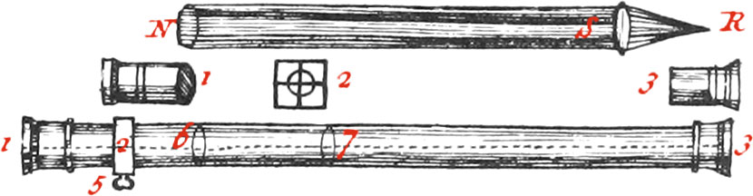
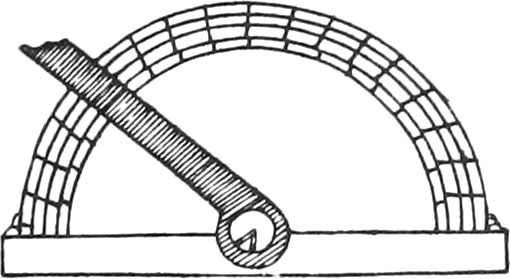
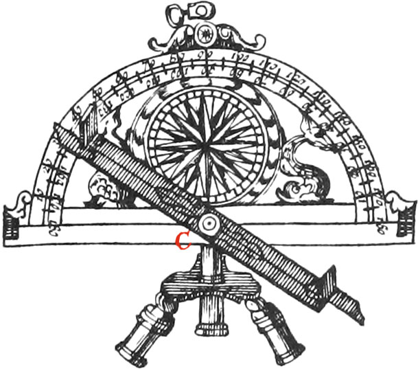
These Instruments which are also called Graphometers, are made of beaten or cast Brass, from 7 Inches Diameter to 15; the Divisions of them are made in the same manner as those of the Theodolite and Quadrant, before explained. The simplest of these Instruments, is that of Fig. K; at the Ends of it’s Diameter, and in little square Holes made upon the fiducial Line, there is adjusted two fixed Sights, fastened with Nuts underneath, and upon it’s Center there is a moveable Index furnished with two other Sights, made in the same manner as those before-mentioned for the Theodolite, and which is fastened with a Screw. There is a Compass placed in the Middle of it’s Surface, for finding the North Sides of Planes. There is also fixed underneath to it’s Center, a Ball and Socket, like that mentioned in the Construction of the Theodolite, and for the same Use.

Note, These Instruments ought to be well straightned with hammering; then they must be fashioned with a rough File, and afterwards smoothed With a Bastard-File, and a fine one. When they are filed enough, you must see whether they are not bent in filing; if they are, they ought to be well straightned upon a Stone, or very plain Piece of Marble; then they must be rubbed over with Pumice-Stone and Water, to take away the Tracts of the File. To polish Semi-Circles well, as also any other Instruments, you must use German-Slate Stone, and very fine Charcoal, so that it does not scratch the Work: afterwards, to brighten them, you must lay a little Tripoli, tempered in Oil, upon a Piece of Shamoy, and rub it over them.

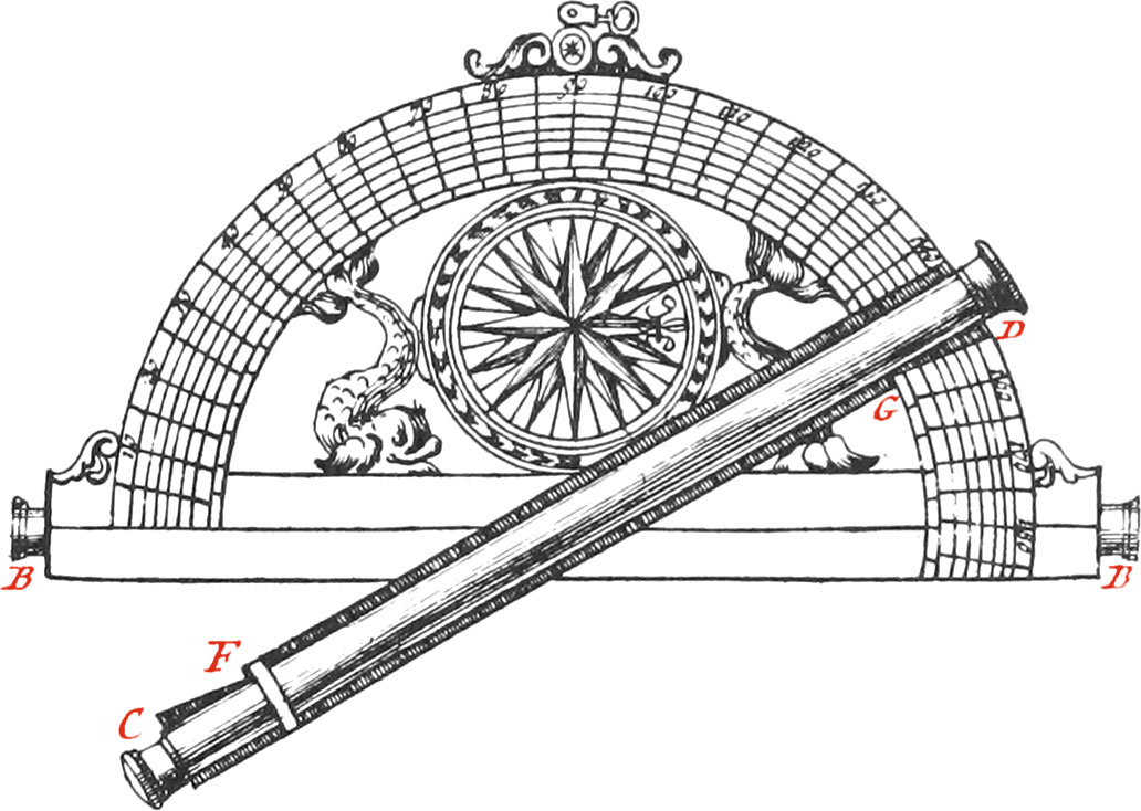
The Semi-Circle I, carries Telescopes for seeing Objects at a good Distance, and has the Degrees of it’s Limb divided into Minutes, by right-lined or curved Diagonals, as in the Quadrant before-mentioned.

There is one Telescope placed underneath along the Diameter of the Semi-Circle, whose Ends are BB; and another Telescope adjusted to the Index of the Semi-Circle. When the fiducial Line cuts the Middle of the Index, the Telescope fastened to it must be a little shorter than the Index, to the End that the Degrees cut by the fiducial Line may be seen; but the best way is for the Telescopes to be of equal Length, and then the fiducial Line must be drawn from the End C, passing thro’ the Center of the Semi-Circle, and terminating in the opposite End D. The two Ends of the Index are cut so as to agree with the Degrees upon the Limb, as may be seen at the places CF, GD, in such manner that the Line CFEGD, may be the fiducial Line of the Semi-Circle.

Note, The Degrees on this Semi-Circle do not begin and end at the Diameter, as in others; but at the Lines CF, GD, when the Telescopes are so placed over each other, that the visual Rays agree. To make which, the little Frame carrying the cross Hairs, must be moved backwards or forwards by means of Screws. The Breadth from the Middle of the Telescope, to the Points F, G, is commonly about 5 Degrees; and this is the Reason why the Divisions begin further from the Diameter than they end, as may be seen per Figure.

These Telescopes have two or four Glasses, and have a very fine Hair strained in the Focus of the Object-Glass, serving for a Sight.

Telescopes with four Glasses shew Objects in their true Situation, but those with two Glasses invert them; so that that which is on the right Hand appears on the left, and that which is above appears below: but this does not at all hinder the Truth of Operations, because they always give the Point of Direction.

Fig. L

These Telescopes are made with Brass Tubes soldered, and turned in a Cylindrick Form 4 as may be seen by the Figure L, which represents a Telescope taken to pieces; the Eye-Glass, being that to which the Eye is applied to look at Objects, is at the End 1. It is put in another little Tube apart (likewise marked 1) which is drawn out, or slid into the Telescope, according to different Sights. This little Tube also sometimes carries the Hair in the Focus of the Glass, serving as a Sight; but it is better for the Hair to be fastened to a little Piece of Brass, (seen apart) on which there is very exactly drawn a square Tract 2, upon which the Hairs are placed. The said Piece is placed in a Groove made in a little Brass Frame, soldered to the Tube of the Telescope at the Place 2; the small Screw 5 is to move forwards or backwards, the little Piece carrying the Hairs; the Object-Glass is placed at the other End of the Telescope, next to the Object to be seen. It is also placed in the little Tube 3, which being put into the Tube of the Telescope, must be binded pretty much by it, that it may not easily change it’s Place when the Telescope is adjusted. The Glasses are convex, which renders their Middle thicker than their Edges; but the Eye-Glass must have more Convexity than the Object-Glass, to the end that Objects may appear greater than by the naked Eye.

The Focus of a Convex Glass is that Place where the Rays, coming from a luminous or coloured Object, unite, after having passed thro’ the Glass; whence the Picture of Objects, opposite to the Glass, are there very distinctly represented. For example, the Point R, at the End of the Cone of the Figure, is the Focus of the Glass S, because it is the Point where the Rays, entering at the other End N of the Tube, unite, after having passed thro’ the Glass S.

The Telescopes most in Use (for Semi-Circles) are those with two Glasses, which are so placed, that their Foci are common, and unite in the same Point in the Tube of the Telescope, in which Point the Hairs are placed; if the focal Length of the Object-Glass is seven or eight times greater than that of the Eye-Glass, the Object will appear seven or eight times greater than when the Foci of the two Glasses are equal.

The Focus of the Eye-Glass being common with that of the Object-Glass, the coloured Rays, which falling upon the Surface of the Object-Glass, and uniting in the Focus of the Glass, afterwards continue their way diverging to the Eye-Glass, and pass thro’ it; so that placing the Eye behind it, Objects may be perceived, whose Pictures are represented in the Focus: for it is the Object that sends forth it’s Species to the Eye, as may be yet very manifestly proved by the following Experiment.

Darken a Room, by shutting the Window-Shutters, and make a round Hole in some Shutter, whose Window is exposed to a Place on which the Sun shines: in which Hole place a Convex Glass, and also a white Piece of Paper or Sheet in the Room, opposite to the Hole, and at the Glass’s focal Distance from it; then a very distinct Representation of all outward Objects, opposite to the Hole in the Shutter, will be painted upon the Paper in the Room in an inverted Situation; and this Picture is made by Rays of Light coming from the Objects without. The focal Distance of the Glass may be found, by moving the Paper backwards and forwards, ’till the Representation of the Objects are distinctly perceived.

There is a Ball and Socket belonging to this Semi-Circle, which, being well made, in the aforesaid manner, is the most perfect that can be made.

Fig. M

The Instrument M is a Protractor about 8 or 10 Inches Diameter, with it’s moveable Index; we make them sometimes as large as Graphometers, and use them both in taking Angles in the Field to a Minute, and also plotting them upon Paper.

The Index of this Protractor turns about a circular Cavity, in the Middle of which is a little Point, shewing the Center of the Protractor. The Divisions of the Limb of this Protractor are made in the same manner as those on the Limb of the Semi-Circle, and by the Method before explained.

Use I.

Fig. 6

To take the Plot of a proposed Field, as ABCDE; plant a Staff very up right, at each Angle of the Field, and measure exactly, with a Toise, one of it's Sides, as AB, which suppose 50 Toises, 2 Feet; then make a Memorial, on which draw a Figure something like the Field proposed: This being done, place the Semi-Circle, with it’s Foot, in the Place of the Staff A; so that looking thro’ the fixed Sights of the Diameter, you may see the Staff B. Afterwards, the Semi-Circle remaining fixed in this Position, turn the Index, so that you may see thro’ the Sights the Staff C. Note the Angle made by the fiducial Line with the Side AB, and write down, in your Memorial, the Quantity of the Angle BAC; afterwards turn the Index so, that you may see the Staff D thro’ the Sights, and write down in your Memorial the Quantity of the Angle BAD: Again, turn the Index so that you may see thro’ the Sights the Staff E, and set down the Quantity of the Angle BAE; but every time you look thro’ the Sights, Care must be taken that the Staff B is in a right Line with the Sights of the Diameter.

This being done, remove the Semi-Circle with it’s Foot, and having replanted the Staffs, place the Semi-Circle, with it’s Foot, in the Place of the Staff B, in such manner, that by looking thro’ the fixed Sights of the Diameter, you may see the Staff A; and the Semi-circle remaining fixed in this Situation, turn, as you have already done, the Index so that you may successively see the Staffs C, D, E, and write down in the Memorial the Quantities of the Angles ABC, ABD, ABE.

Finally, Plot the Field exactly with a Semi-Circle or Protractor, by laying down all the Angles, whose Quantities are marked at the Ends of the Line AB, from whence may be drawn as many right Lines, and from their Intersections other Lines, which will form the Plot of the Field proposed. The Lengths of all those Sides which have not been measured, may be found by a Scale of equal Parts, of which the Line AB is 50\(\frac{1}{3}\) and the Area of the Field may be found by finding the Area of all the Triangles it may be reduced into.

Note, It is proper to measure one of the longest Sides of the Field, for using it as a common Base, and making at both it’s Ends all the Observations necessary for there forming the Angles of the Triangles required to be made; for if one of the shortest Lines be taken for a common Base to all the Triangles, the Angles formed by the Intersections of the visual Rays in looking at the Staffs, will be too acute, and so their Intersections very uncertain.

The Meridian Line of Plans may be known by help of the Compass, whose Meridian is generally parallel to the Diameter of the Semi-Circle: for since the common Base of all the Triangles observed, is parallel to the said Diameter, you need but note the Angle which it makes with the Needle of the Compass, and this may be easily done by directing the fiducial Line parallel to the Needle; after which you may draw upon the Plot a little Card in it’s true Position.

Use II. To find the Distance from the Steeple A to the tower C, they being supposed inaccessible.

Fig. 7

Having chosen 2 Stations, from which the Steeple and Tower may be seen, and measured their Distance serving as a Base, place the Semi-Circle at one of them, as D, and the Staff in the other, as in the Point E, and turn it so, that thro’ the fixed Sights of it’s Diameter, or thro’ the Telescope, you may espy the Staff E: then move the Index so, that thro’ it’s Sights you may see the Steeple A; and the Degrees of the Semi-Circle between the Diameter and the Index, will give the Quantity of the Angle BDE, being in this Example 3 Deg. which note in your Memorial. Again; turn the Index ’till you see the Tower C thro’ the Sights or Telescope, always keeping the Diameter in the Line DE; then the Degrees between the Diameter and Index, will shew the Quantity of the Angle CDE, 123 Deg. which likewise note in the Memorial. Now having removed the Semi-Circle from the Station D, and placed a Staff in it’s Place, measure the Distance from the Staff D to the Staff E, which suppose 32 Toises, writing it in the Memorial: then put the Semi-Circle in the Place of the Staff E, so that the fixed Sights of the Diameter, or Telescope, may be in the Line ED; and turn the Index, that the Tower C may be seen thro’ it's Sights, then the Degrees contained between the Diameter, and the Index, will give the Angle CED, which in this Example is 26 Degrees. Finally, Turn the Index ’till you see the Steeple A thro’ the Sights, and the Angle AED will be 125 Degrees, which set down in the Memorial, and by help of a Scale and Protractor, the Distance AC may be known.

To solve the same Problem trigonometrically; first, We have found by Observation in the Triangle DAE, that the Angle ADE is 32 Degrees, and the Angle DEA 125 Degrees, whence the Angle DAE is 23 Degrees (because the three Angles of any right-lined Triangle, are equal to 2 right Angles), and to find the Side AE, make this Analogy: As the Sine of 23 Degrees is to 32 Toises, So is the Sine of 32 Degrees to the Line AE, about 43 Toises. Likewise you will find by Observation in the Triangle CDE, that the Angle CDE is 26 Degrees, and the Angle EDC 123 Degrees, whence the Angle DCE is 31 Degrees; and to find the Side CE, make this second Analogy: As the Sine of 31 Degrees is to 32 Toises, So is the Sine of 123 Degrees, or it’s Complement 57, which is the fame, to CE 52 Toises. Now to find the Distance CA, examine the Triangle CAE, whose two Sides CE, AE, with the included Angle AEC of 99 Degrees, are known, and consequently the Sum of the two unknown Angles are equal to 81 Degrees; and to find either of them, make again this Analogy: As the Sum of the two known Sides 95 Toises, is to their Difference 9, So is the Tangent of 40 Deg. 30 Min. half the Sum of the opposite Angles, to the Tangent of half their Distance, which answers to 4 Deg. 37 Min. and being added to 40 Deg. 30 Min. will give the greatest of the unknown Angles CAE, 45 Deg. 7 Min. and consequently the other Angle ACE, will be 35 Deg. 53 Min. Lastly, to find the Length CA, say, As the Sine of 35 Deg. 53 Min. is to 43 Toises, So is the Sine of 99 Deg. to the Distance AC, 72 Toises, 2 Feet.

Use III.

Fig. 8

To find the Height of the Tower AB, whose Base cannot be approached because of a Rivulet passing by it’s Foot; chuse two Stations somewhere upon level Ground, as in C and D, and place the Semi-Circle vertically in the Point D, so that it's Diameter may be parallel to the Horizon, which you may do by means of a Thread and Plummet, hung on the Top of a Perpendicular drawn on the backside of the Semi-Circle: then turn the Index, in order to see the Top of the Tower B thro’ the Sights, and take the Quantity of the Angle BDA, which suppose 42 Degrees, noting it down in your Memorial. Now having removed the Semi-Circle, and placed it at the other Station C, measure the Distance DC, which suppose 12 Toises, and after having adjusted the Semi-Circle, so that it’s Diameter may be parallel to the Horizon, turn the Index ’till you see the Top of the Tower B, and set down the Quantity of the Angle BCD, which suppose 22 Degrees, in the Memorial; then make a similar Figure by means of a Scale and Protractor, and the Height of the Tower AB will be found; which may likewise be found by Calculation in the following manner: The Angle BDA of 42 Degrees, gives the Angle BDC of 138 Degrees; and since the Angle C of 22 Degrees has been measured, the third Angle of the Triangle CBD will be 20 Degrees. Now say, As the Sine of 20 Degrees is to 12 Toises, So is the Sine of 22 Degrees, to the Line BD, about 13 Toises; but BD is the Hypothenuse of the right-angled Triangle BDA, all the Angles of which are known: therefore say by a second Rule of Three, As Radius is to about 13 Toises, So is the Sine of 42 Degrees to the Height AB, 8 Toises, and one Foot.

Use IV. To make the Map of a Country.

Fig. 9

First, chuse 2 high Places, from whence a great Part of the Country may be seen, which let be so remote from each other, as that their Distance may serve as a common Base to several Triangles that must be observed for making of the Map;, then measure with a Chain the Distance of these two Places. These two Places being supposed A and B, distant from each other 200 Toises, place the Plane of the Semi-Circle horizontally, with it’s Foot in the Point A, in such manner, that you may discover the Point B thro’ the fixed Sights or Telescope: the Instrument remaining fixed in this Situation, turn the Index, and successively discover Towers, Steeples, Mills, Trees, and other remarkable Things desired to be placed in the Map: examine the Angles which every of them make with the common Base, and set them down together with their proper Names in the Memorial: As, for Example, the Angle BAI 14 Degrees, BAG 47, BAH 53, BAF 68, BAE 83, BAD 107; and, lastly, the Angle BAC 130 Degrees: which being done, and the Distance of the two Stations AB set down, place the Semi-Circle in the Point B, for a second Station.

The Instrument being so placed that it's Diameter may be in the Line BA, turn the Index, and observe the Angles made by the Objects before seen from the Point A; as for Example, the Angle ABC 20 Degrees, ABF 37, ABD 44, ABE 56, ABG 83, ABH 96, and the Angle ABI 133 Degrees, which note down in the Memorial.

If any Object viewed from the Point A, cannot be seen from the Point B, the Base must be changed, and another Point sought, from whence it may be discovered; for it is absolutely necessary for the same Object to be seen at both Stations, because it’s Position cannot be had but by the Intersection of two Lines drawn from the Ends of the Base, with which they form a Triangle.

Note, The Base must be pretty long, in proportion to the Triangles for which it serves, and moreover very straight and level.

To make the Map, reduce all those Triangles observed, to their just Proportion, by means of a Scale and Protractor, in the manner as we have already given Directions, in the Use of the Theodolite.

  1. Previous Book IV. Chapter V. Quadrant and Geometrick Quradrat
  2. Contents
  3. Next Book IV. Chapter VII. Compass