Mathematical Instruments
Book V. Ch. II.

Of the Uses of the aforesaid Instruments in Levelling.

Fig. 1

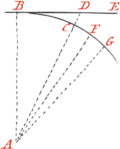
Levelling is an Operation shewing the Height of one Place in respect to another. One Place is said to be higher than another, when it is more distant from the Center of the Earth. A Line equally distant from the Center of the Earth, in all it’s Points, is called the Line of true Level; whence, because the Earth is round, that Line must be a Curve, and make a part of the Earth’s Circumference, as the Line BCFG, all the Points of which are equally distant from the Center A of the Earth: but the Line of Sight, which the Operations of Levels give, is a right Line perpendicular to the Semi-Diameter of the Earth AB, raised above the true Level, denoted by the Curvature of the Earth, in proportion as it is more extended; for which Reason, the Operations which we shall give, are but of the apparent Level, which must be corrected to have the true Level, when the Line of Sight exceeds 50 Toises.

The following Table, in which are denoted the Corrections of the Points of apparent Level, for reducing them to the true Level, was calculated by help of the Semi-Diameter of the Earth, whose Length may be known by measuring one Degree of it’s Circumference. The Gentlemen of the Academy of Sciences, have found by very exact Observations, that one Degree of the Circumference of a great Circle of the Earth, as the Meridian, contains 57292 Toises; and giving 25 Leagues to a Degree, a League will be 2291\(\frac{17}{25}\) Toises.

Now the whole Circumference of the Earth will be 9000 of the same Leagues, and it’s Diameter 2863\(\frac{7}{11}\) of them; from whence all Places on the Superficies of the Earth, will be distant from it’s Center 142\(\frac{15}{44}\) Leagues.

The Line AB represents the Semi-Diameter of the Earth, under the Feet or the Observer. The right Line BDE, represents the visual Ray, whose Points D and E are in the apparent Level of the Point B. This Line of apparent Level, serves for determining a Line of true Level, which is done by taking from the Points of the Line of apparent Level, the Height they are above the true Level in respect to a certain Point, as B; for it plainly appears from the Figure, that all the Points D, E, of the apparent Level, are farther distant from the Center of the Earth, than the Point B; and to find the Difference, you need but consider the right-angled Triangle ABD, whose two Sides AB, BD, being known, the Hypothenuse AD, may be found: from which substracting the Radius AC, the Remainder CD will shew the Height of the Point D of apparent Level, above the Point of true Level.

The Rule serving to calculate this Table, is to divide the Square of the Distance by the Diameter of the Earth, which is 6,565,179 Toises; for which Reason the Corrections are to one another, as the Squares of the Distances. Altho’ the Foundation of this Calculation be not strictly Geometrical, yet it is nigh enough the Truth for Practice.

Distances of the Points of apparent Level Corrections
Inches Lines
50 Toises00
100 Toises01\(\frac{1}{3}\)
150 Toises03
200 Toises05\(\frac{1}{3}\)
250 Toises08\(\frac{1}{3}\)
300 Toises10
350 Toises14\(\frac{1}{3}\)
400 Toises19\(\frac{1}{3}\)
450 Toises23
500 Toises29
550 Toises36
600 Toises40
650 Toises48
700 Toises54
750 Toises63
800 Toises71
850 Toises711\(\frac{1}{2}\)
900 Toises811
950 Toises100
1000 Toises110

If the Points of apparent Level should be taken instead of the Points of true Level, a Body would err in conducting the Water of a Source, which let be, for Example, at the Point B; for this Source will not run along the Line BDE, but will remain in the Point B; for if it should run along the Line BE, it would run higher than it is, which is impossible, because it cannot be endued with any other Figure but a Circular one, equally distant from the Center of the Earth. On the contrary, a Source in D will have a great Descent down to the Point B; but it cannot run further, because it must be elevated higher than the Source, if it continues it’s way in the same right Line, which cannot be done, unless it be forced by some Machine.

How to rectify Levels.

Fig. 2

To rectify Levels, as, for Example, The Air-Level C you must plant two Staffs, as AB, about 50 Toises distant from each other, because of the Roundness of the Earth (take care of exceeding that Distance), then espying from the Station A, the Point B, the Level being placed horizontally, and the Bubble of Air being in the Middle of the Tube, you must raise or lower a Piece of Pasteboard upon the Staff B, in the Middle of which is drawn a black horizontal Line, ’till the visual Ray of the Observer’s Eye meets the said Line; after which must be fastened another Piece of Pasteboard to the Staff A, the Middle of which let be the Height of the Eye, when the Piece of Pasteboard B was seen: then removing the Level to the Staff B, place it to the Height of the Center of the Pasteboard, and the Level being horizontally posited for observing the Piece of Pasteboard A, if then the visual Ray cuts the Middle of the Piece of Pasteboard, it is a sign the Level is very just; but if the visual Ray falls above or below, as in the Point C, you must, by always keeping the Eye at the same Height, lower the Telescope or the Sight, ’till the Middle of the visual Ray falls upon the Middle of the Difference, as in D; and the Telescope thus remaining, the Tube of the Level must be adjusted ’till the Bubble of Air fixes in the Middle, which may be done by means of the Screw 4.

Again; Return to the Staff A, and place the Level the Height of the Point D, for looking at the Piece of Pasteboard B; and if the visual Ray falls upon the Middle of the Piece of Pasteboard, it is a sign the Telescope agrees with the Level: if not, the same Operations must be repeated, until the visual Rays fall upon the Centers of the two Pieces of Pasteboard.

Another way to rectify Levels.

Knowing two Points distant from each other, and perfectly level, place the End of the Telescope carrying the Eye-Glass to the exact Height of one of those two Points, the Bubble of Air being fixed in the Middle of it’s Tube; then by looking thro’ it, if it happens that the Hair of the Telescope cuts the second Point, it is a sign the Level is just; but if the Hair falls above or below the Point of Level, you must, in always keeping the Eye at the same Height, raise or lower the End of the Level where the Object Glass is, until the Visual Ray of the Telescope falls upon the exact Point of Level; and leaving it thus, raise or depress the Tube carrying the Level, so that the Bubble of Air may remain in the Middle.

What we have said concerning the Rectification of this Level, may serve likewise for the Rectification of others, the Difference is only to change the Plummets and the Hairs of the Telescopes, according to their Constructions.

The Manner of Levelling.

Fig. 3

To find, for Example, the Height of the Point A on the Top of a Mountain, above the Point B at it’s foot, place the Level about the middle Distance between the two Points, as in D, and plant Staffs in A and B. Also let there be Persons instructed with Signals, for raising or lowering upon the said Staffs slit Sticks, at the Ends of which are fastened pieces of Paste-Board: The Level being placed upon it’s Foot, look towards the Staff AE, and cause one of the Persons to raise or lower the Paste-Board, until the upper Edge or Middle appears in the visual Ray; then measure exactly the perpendicular Height of the Point E above the Point A, which, in this Example, suppose 6 Feet 4 Inches, which set down in a Memorial. Then turn the Level horizontally, so that it may always be at the same Height, for the Eye-Glass of the Telescope to be next to the Eye; but if it be a Sight Level, there is no necessity of turning it about, and cause the Person at the Staff B to raise or lower the Piece of Paste-Board, until the upper Edge of it be seen, as at C, which suppose 16 Feet 6 Inches, which set down in the Memorial above the other Number of the first Station; whence to know the Height of the Point A above the Point B, take 6 Feet 4 Inches from 16 Feet 2 Inches, and the Remainder will be 10 Feet 2 Inches, for the Heighth of A above B.

Note, If the Point D, where the Observer is placed, be in the Middle between the Point A and the Point B, there is no necessity of regarding the Height of the apparent Level above the true Level, because those two Points being equally distant from the Eye of the Observer, the visual Ray will be equally raised above the true Level, and consequently there needs no Correction to give the Height of the Point A above the Point B.

Another Example of Levelling.

Fig. 4

It is required to Know, whether there be a sufficient Descent for conducting Water from the Source A to the Receptacle B of a Spring. Now because the Distance from the Point A to B is great, there are several Operations required to be made. Having chosen a proper Height for placing the Level, as at the Point I, plant a Pole in the Point A near the Source, on which slide up and down another, carrying the Piece of Paste-Board L; measure the Distance from A to I, which suppose 1000 Toises. Then the Level being adjusted in the Point K, let somebody move the Paste-Board L up or down, until you can espy it thro’ the Telescope or Sights of the Level, and measure the Height AL, which suppose 2 Toises, 1 Foot, 5 Inches. But because the Distance AI is 1000 Toises, according to the aforementioned Table, you must substract 11 Inches, and the Height AL will consequently be but 2 Toises 6 Inches, which note down in the Memorial.

Now turn the Level about, so that the Object Glass of the Telescope may be next to the Pole planted in the Point H, and the Level being adjusted, cause some Person to move the Piece of Paste-Board G up and down, until the upper Edge of it may be espied thro’ the Telescope; measure the Height HG, which suppose 3 Toises, 4 Feet, 2 Inches; measure likewise the Distance of the Points I, H, which suppose 650 Toises; for which Distance, according to the Table, you must substract 4 Inches 8 Lines from the Height HG, which consequently will then be but 3 Toises, 3 Feet, 9 Inches, 4 Lines, which set down in the Memorial.

This being done, remove the Level to some other Eminence, from whence the Pole HG may be discovered, and the Angle of the House D, the Ground about which is level with the Receptacle B of the Spring.

The Level being adjusted in the Point E, look at the Staff H, and the visual Ray will give the Point F; measure the Height HF, which suppose 11 Feet 6 Inches; likewise measure the Distance HE, which suppose 500 Toises, for which Distance the Table gives 2 Inches 9 Lines of abatement, which being taken from the Height HF, and there will remain 11 Feet, 3 Inches, 3 Lines, which set down in the Memorial. Lastly, Having turned the Level for looking at the Angle of the House D, measure the Height of the Point D, where the visual Ray terminates above the Ground, which suppose 8 Feet 3 Inches. Measure also the Distance from the Point D, to the said House, winch is 450 Toises, for which Distance the Table gives 2 Inches 3 Lines of Abatement; which being taken from the said Height, there will remain 8 Feet 9 Lines, which set down in the Memorial.

How to set down all the different Heights in the Memorial.

Having found proper Places (as we have already supposed) for placing the Level between two Points, you must write on the Memorial, in two different Columns, the observed Heights; namely, under the first Colum those observed by looking thro’ the Telescope, when the Eye was next to the Source A; and under the second Column, those observed when the Eye was next to the Receptacle B of the Spring, in the following Manner.

First Column.
Toises Feet Inches Lines
First Height Corrected 2 0 6 0
Third Height 1 5 3 3
3 5 9 3
Second Column.
Toises Feet Inches Lines
Second Height 3 3 9 7
Fourth Height 1 2 0 9
4 5 1 01

Having added together the Heights of the first Column, and afterwards those of the second, substract the first Additions from the second.

First Column.
Toises Feet Inches Lines
4 5 10 1
3 5 9 3
1 0 0 10

Whence the Height of the Source A above the Receptacle B is 1 Toise and 10 Lines.

If the Distance be required, you need but add all the Distances measured together; namely,

$$ \begin{array}{r} &\text{The First of }\ 1000\text{ Toises}\\ &\text{The Second}\ \ \ \ \ 650\ \ \ \ \ \ \ \ \ \ \ \ \\ &\text{The Third}\ \ \ \ \ 500\ \ \ \ \ \ \ \ \ \ \ \ \\ &\text{The Fourth}\ \ \ \ \ 450\ \ \ \ \ \ \ \ \ \ \ \ \\ \hline &\text{The whole Distance}\ \ 2600\text{ Toises} \end{array} $$

Lastly, Dividing the Descent by the Toises of the Distance, there will be for every 100 Toises, about 2 Inches 9 Lines of Descent, nighly.

  1. Previous Book V. Chapter I. Levels
  2. Contents
  3. Next Book V. Chapter III. Water Gauge