Of the Construction and Uses of the Astronomical Quadrant.
The Quadrants used by Astronomers for Celestial Observations, are usually three Feet, or three Feet and a half (of Paris) Radius, that so they may be easily managed and carried from Place to Place. Their Limbs are divided into Degrees and Minutes, that so Observations made with them may be very exact.
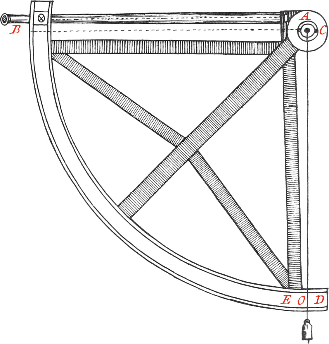
Fig. 1
This Instrument is composed of several pretty thick Iron or Brass Rulers, whose Breadths ought to be parallel to it’s Plane. There are moreover other Iron or Brass Rulers, so adjusted and joined behind the former ones, that their Breadths are perpendicular to the Plane of the Quadrant. These Rulers are joined together by Screws, by means of which the whole Conjunction of the Instrument is made, which ought to be very strait every way, firm, and pretty weighty. The Limb is likewise strengthened with a curved Brass, or Iron Ruler. There is a thick strong circular Blade placed in the Center, serving for the Uses hereafter mentioned; which circular Blade and the Limb must be railed something higher than the Plane of the Instrument, both of which must be covered with well-polished thin Pieces of Brass. But you must take great care that the Surfaces of these Pieces of Brass be both in the same Plane.
The aforesaid circular Iron Blade in the Center must have a round Hole in the Middle thereof, about \(\frac{1}{2}\) of an Inch in Diameter, in which is placed a well-turned Brass Cylinder, raised something above the central thin Piece of Brass.
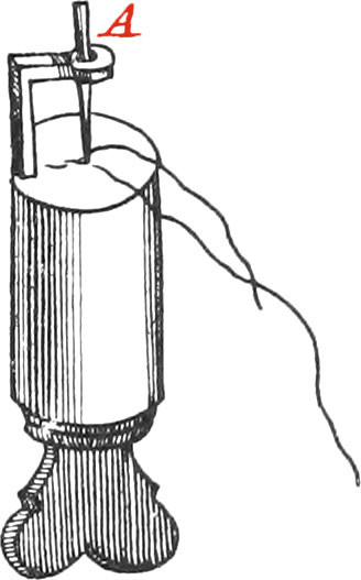
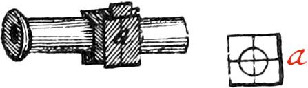
Fig. 2
This Cylinder, which is represented in Figure 2, hath the Point of a very fine Needle adjusted in the Center of it’s Base, which is supported in going into a little Hole in the Center of the Base, and by lying along a semi-circular Cavity, and is kept therein by means of a little Spring pressing against it; so that when the Needle is taken away, and we have a Mind to put it there again, it may exactly be placed in the little Hole in the Center of the said Cylinder. This little Hole ought to be no bigger than a Hair, but it must be something deep, that so the Point of the Needle may go far enough into it, that at the making of the Quadrant it may not come out. At the Point of this Needle is hung a Hair, by means of a Ring made with the same Hair big enough, for fear left the Knot of the Ring should touch the central Plate, and the Motion of the Hair be disturbed. Note, The Base of the central Cylinder A, represented in this Figure, must be such, that the Ring of the Hair, hung on the Point of the Needle, may not touch the said Base otherwise than in it’s Center, when there is a Plummet hung to the End of the Hair, of about half an Ounce in weight.
The Construction of this central Cylinder ought to be such, that it may be taken away and preserved, and another placed instead thereof, of the same Thickness therewith, but something longer; which coming out beyond the central Blade, sustains the Ruler of the Instrument, in such manner as we are going to explain.
Figs. 3 & 5
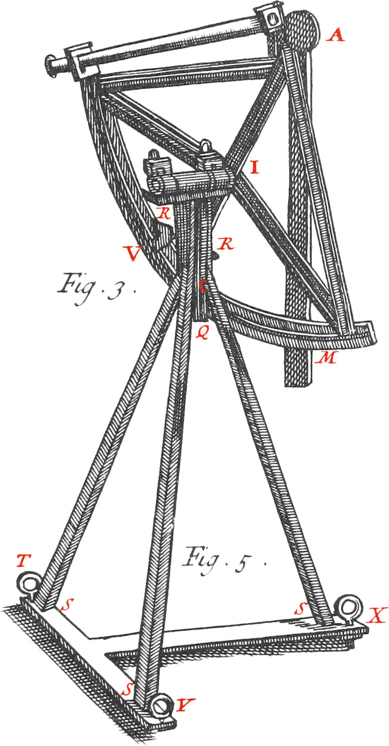
There is moreover, at the central Brass Blade, which covers the Iron one, a plane Ring turning about the Center, but not touching the central Cylinder; in such manner, that the outward Surface thereof is even with the Surface of the said Brass Blade. Upon this Ring is fastened, with two Screws, a flat Tube M, which moves freely along with the Hair and Plummet, which it covers, and so preserves it from the Wind when the Instrument is using.
This Tube carries a Glass, placed against the Divisions of the Limb of the Quadrant, in order to see what Point of Division the Hair falls upon. Behind, and nigh to, the Center of Gravity of the Quadrant, is firmly fixed, with three or four Screws, to the Rulers of the Instrument, the Iron Cylinder I, whose Length is 8 Inches, and Diameter of it’s Base two Inches. This Cylinder being perpendicular to the Plane of the Quadrant, may be called it’s Axis.
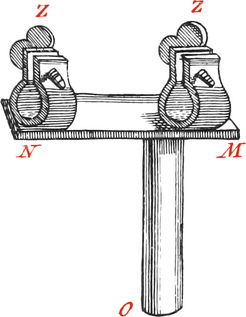
Fig. 4
Now because the principal Use of this Instrument is for taking the Altitudes of the Sun or Stars, it must be so ordered, that it’s Plane may be easily placed in a vertical Situation; therefore an Iron Ruler MN must be prepared, whole Thickness is three Lines, Length eight Inches, and Breadth one Inch, or thereabouts. On one Side of this Ruler are adjusted two Iron Rings ZZ, open a-top with Ears, each of which has a Screw to draw the Ears closer together, which have a Spring. The Bigness of these Rings is nearly equal to the Thickness of the Cylinder I, or Axis of the Quadrant, which being put thro’ them, is made fast with the Screws; so that the Axis and Quadrant, which it is fixed to, may remain firm in any Position the Quadrant is put into.
On the other Side of the said Ruler MN is soldered an Iron Cylinder O, of such a Length and Breadth, as to go into the Tube Q, of which we are going to speak.
Figs. 3 & 5
Now when the Instrument is to be placed so, that it’s Plane may be horizontal, for using an Index or moveable Arm to take the Distances of Stars or Places upon Earth, the Cylinder I. must be put into the Tube Q, by which means the Quadrant may be easily turned to what part you please.
The Foot, or Support of the whole Instrument, is commonly composed of an Iron Tube Q; whose upper Part is capable of containing the Cylinder O, and it’s lower Part goes thro’ the Middle of an Iron Cross, and is fastened in it by four Iron Arms, at the four Ends of which Cross are four great Screws, to raise or lower the Quadrant, and put it in a convenient Situation. But Monsieur de la Hire proposes a Triangular Support in his Tables, which is composed of an Iron or Brass Tube, big enough to contain the Cylinder O, fastened with two Screws to three Iron Rulers RS, bent towards their Tops, and of a pretty good Thickness, which are adjusted and well fixed to a Tee or double Square TXY. The Screw V, in the Middle of the Tube Q, is for fixing the Cylinder O, according to Necessity.
Now when the Meridian Altitudes of Stars are to be observed, the Ruler TY ought to be placed in the Meridian Line, and of the three Screws TXY, which sustain the Weight of the whole Instrument; that which is in X serves to lower the Plane of the Instrument, ’till it answers to the Plane of the Meridian, according as the Observer would have it; and the other two are for raising or lowering the Instrument by little and little, until the Plumb-Line falls upon the requisite Altitude. But it often happens in turning the Screws that are in T and Y, that the Quadrant displaces itself from it’s true Position; whence, if the Defect be some Minutes, this may be remedied, by hanging a moveable Weight to the Backside of. the Branches of the Instrument, which may alter the Center of Gravity, as likewise change the Inclination of the Quadrant; for the Rulers composing the Foot are not entirely free from Elasticity. Now the nigher to the Foot the Place of Suspension of the Weight is, the less Force will it have to shake the Instrument. Note, The Height of the Foot is commonly four Feet and a half, or thereabouts, and the same Use is equally made of the four Branch Support.
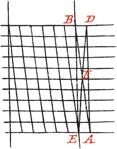
Fig. 6
The Divisions on the Limb of this Quadrant ought to be made with great Care, that so Observations may thereby be exactly taken. Each Degree is divided into 60 Minutes, by means of 11 concentrick Circles, and 6 Diagonal right Lines, as in Figure 6 may be seen. These Diagonal Distances are equal between themselves, but those of the Concentrick Circles are unequal; yet this Inequality is not sensible, if the Radius of the Quadrant be three Feet, and the Distance between the two outmost concentrick Circles be one Inch; for if the Arc AE, of the outmost Circle be 10 Minutes, and there are drawn, from the Center C of the Quadrant, the Radii ADC, EBC, meeting the inner concentrick Circle in the Points D, B, the Arc DB will be likewise 10 Minutes. Note, Figure 6 is supposed to be put upon the Limb of the Instrument, Figure 1.
But if the Right-lined Diagonals AB, DE, are drawn intersecting each other in the Point F; I say F is the middle Point or Division thro’ which the middle Circle ought to pass: For the Arcs AE, BD, which may be taken for strait Lines, are to each other, as AF is to FB: for it is evident, that CA is to CB, as the Divisions of the Base AB of the Right-lined Triangle ACB; bur since CA is to CB as AE is to DB, therefore AE is to DB, as the Divisions of the Base AB made by a Radius, bisecting the Angle ACB: and consequently the Point F, before found in the Right-lined Diagonal AB, will be the middle Point of the Divisions.
Now let us suppose, that AC be to CB, as 36 Inches is to 35; then AB is to AF, as 71 is to 36. Therefore if the Breadth of one Inch, or 12 Lines, which is the supposed Measure of AB, be divided into 71 equal Parts, the Part AF will be 36 of them, which will be greater by half, or about \(\frac{1}{12}\). of a Line, than half of AB, which is but 35\(\frac{1}{2}\). This Difference is of no consequence, and may, without any sensible Error, be neglected in the Division of the Middle; and much more in the other Divisions, where it is less.
Instead of making Right-lined Diagonals, we may make them Portions of Circles passing thro’ the Center of the Instrument, and the first and last Point of the same Diagonal; then we need but divide the first Circular Portion into ten equal Parts, and the exact Points will be had thro’ which the eleven Concentrick Circles must pass.
The Radius of this first Portion may be easily found; and then if a thin Ruler be bent into the Curvature thereof, all the other Portions may be drawn by means of it, as we have already mentioned in speaking of the Divisions of Quadrants, Semi-Circles, &c.
Note, It will be proper to leave, at the Bottom of the Limb, the Points that were made for drawing every 10th Minute; for these will be a means to take the Correspondent Altitudes of the Sun, Morning and Evening, much exacter than can be done by the Diagonals, because of the Estimation thereby avoided. Moreover, there may be some fault in the Diagonals which there cannot be in the Points, if care be taken in making them: for it is difficult enough to draw the Diagonals exactly thro’ those Points they should pass. For which reason, if a Micrometer be joined to the fixed Telescope of the Instrument, the Diagonals need not be used, and the aforesaid Points will be sufficient; since the Micrometer will give, by means of a moveable Hair, the Interval between the nearest of one of the aforesaid Points, at every 10th Minute, and the Plummet. And this is done by raising or lowering the moveable Hair above or below the horizontal Hair, 10 Minutes of a Degree, or a little more. The Chevalier de Louville, of the Academy of Sciences, hath satisfactorily used a Quadrant for his Observations, constructed in this Manner.
We now come to speak of the Telescopes, and the Manner of finding the first Point of the Divisions of the Limb of the Quadrant.
These Telescopes have each two Glasses, one of which is the Object-Glass, placed towards the visible Object, and near to the Center of the Quadrant; and the other is the Eye-Glass, placed at the other End or the Telescope, next to the Eye of the Observer.
The Object-Glass is firmly fastened in an Iron Frame, which is fixed with Screws about the Center of the Instrument. Near the Eye-Glass are placed two fine Hairs, crossing each other at Right Angles, in an iron Frame, to which they are fastened with Wax upon a little piece of Brass; so that the one is perpendicular to the Plane of the Instrument, and the other parallel thereto.
The Eye-Glass must be placed in a Tube, that so it may be moved backwards or forwards, according to different Sights; and the Distance between the Object-Glass and Cross-Hairs, must be the said Glass’s Focal Length; that is, the Cross-Hairs must be placed in the Focus of the Object-Glass. These Telescopes must be so disposed, that the Surfaces of the Lenses (as Planes) and the Planes in which are the Cross-Hairs, be parallel to each other, and perpendicular to Right Lines drawn thro’ the Centers of the Lenses, and the Points wherein the Hairs cross each other. These Telescopes are adjusted behind the Quadrant, that so the divided Brass-Limb may not be incumbered by them.
Between the Frames sustaining the Glasses, is a Brass or Iron Tube, composed of two Parts, one of which is inchased in the other, that so they may easily be taken from between the Frames, by means of Ferrels keeping them together.
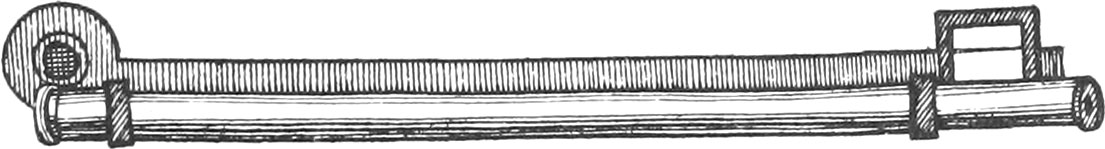
The Convex Eye-Lens must be brought nearer, or removed further from the Cross-Hairs, according to the diverse Constitutions of Observators Eyes; that so distant Objects may be distinctly perceived, as likewise the Cross-Hairs. This Eye-Glass is placed in another little moveable Tube, the greatest part of which lies concealed in another Tube, as may be seen in Fig. 7.
Fig. 7
When the Eye-Glass wants cleansing, or the Cross-Hairs are broken or disordered, and others to be put in their place, the before-mentioned Brass or Iron Tube must be taken from between the Frames.
But the Construction of the Eye-Glass will be much more convenient, if, instead of a Frame only, you use a little square Box, about four Lines in Thickness, whose two opposite Sides, which are parallel to the Limb of the Quadrant, have Grooves along them, in which may move a little Plate of a mean Thickness, drilled thro’ the Middle with a round Hole of a convenient bigness.
Upon the Surface of this Plate, represented by the Figure a, are continued out two Diameters of the aforesaid Hole, eroding each other at Right Angles, one of which is parallel to the Limb, and the other perpendicular thereto, upon which are placed the Cross-Hairs. This Plate is very useful for moving the said Cross-Hairs, strained at Right Angles a-cross the Middle of the Hole, backwards or forwards, according to necessity. And when the Hairs are placed as they should be, the aforesaid Plate is fixed to the Box with Wax, which ought to be furnished with a sliding Cover, for keeping the Cross-Hairs from Accidents.
The Inside of the Tube ought to be blackened with the Smoke of Rosin, in order to preserve the Eye from too strong Rays which come from a luminous Object, that so the Appearance thereof may be more perfect. Note, Instead of having Cross-Hairs in the before-mentioned Box, a little Piece of plain Glass may be used, having two fine Lines drawn upon it at Right Angles with the Point of a Diamond.
The Telescope being prepared and placed in a convenient Situation parallel to the Radius, or Side of the Quadrant; the next thing to be done, is to find the first Point of the Divisions of the Limb of the Quadrant, which is 90 Degrees distant from the Line of Collimation or Sight of the Telescope, or a Line parallel to it, passing thro’ the Center of the Quadrant. But, First, it will be necessary to say something concerning this Line of Collimation, or Sight, about which M. de la Hire says, he had formerly a long Controversy, with very celebrated and great Astronomers, who, for want of duly considering Dioptricks, maintained, that it is impossible to find a settled and constant Line of Collimation in these kind of Telescopes.
Fig. 8
It is now manifest, that all the Rays proceeding from any one Point of an Object, after having passed thro’ the Glass Lens, will all concur in one and she same Point, which is called the Focus, provided that the Distance of the Radiating Point from the Lens be greater than the Semidiameter of either of the Convexities of the Lens, which here we suppose equal; that besides, among the Rays coming from a Radiating Point, and falling upon the anterior Surface of the Glass, that which concurs with a Line passing thro’ the Centers of the Convexities, will suffer no Refraction at it’s going in or coming out of the Glass; therefore the Points of Objects that are in that Right Line, are represented in the same Line, which is called the Axis of the Optick Tube, and the Point of the Axis which is in the Middle of the Glass’s thickness, is called the Center of the Lens.
If the Right Line passing thro’ the Center of the Lens, and the Point where the Hairs cross one another, agree with the Axis of the said Optick Tube, it will be the Line of Collimation of the Telescope; and an Object very distant, placed in the Axis produced, will appear in the same Point where the Hairs cross one another: just as in common Indexes, where we take For the Line of Sight, the Right Line, that passing thro’ the Slits of the Sights, tends to the Object. But altho’ it almost never happens in the Position of Telescopes, which we have established, that the Right Line tending from the Object to the Point wherein the Hairs cross, and whereat the Object is represented, coincides with the Optick Axis; nevertheless we shall not desist finding that Line of Collimation tending from the Object to it’s Picture, represented in the Point wherein the Hairs cross each other; which may be done in the following Manner.
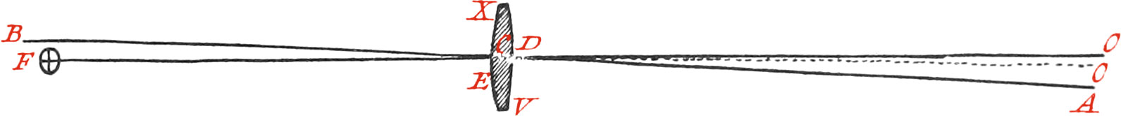
Let XV be a Glass Lens, it’s Axis ACB, and it’s Center C; let F be the Point wherein the Hairs cross one another without the Axis ACB. If from the Point F, which by Construction is at the Focal Distance from the Lens, Rays pass thro’ the Glass, they will suffer a Refraction at their Entrance into the Glass, and a second Refraction at their going out thereof; after which, they will continue their way parallel to one another. Now there is one of these Rays, namely, FE, which coming from the Point F, after the first Refraction in the Point E, passes thro’ the Center C; for after a second Refraction at it’s going out of the Glass in the Point D, it will continue it’s way from D to O, parallel to FE, according to Dioptrick Rules. But all the Rays separated at their going out of the Glass may be taken as parallel, if they tend to a very distant Point O, therefore they are also parallel to the Ray FEO, which is produced from the Object directly to the Point O; and it is this Right Line FEO, which we call the Line of Collimation, in the aforesaid Position of Telescopes, and it will always remain the same, if the Situation of the Glasses be not changed, that is, if the Lens and the Cross-Hairs are in the same Position and Distance. The Object O being in one of the extreme Points of the Right Line FEO, will be represented in the Point F.
Note, The Distance between the principal Ray OD, falling from the Point O of the Object upon the Lens, and it’s refracted Ray EF, is always lesser than the Thickness of the said LensDE, which is insensible, and of no Importance, in the Distance of a very distant Object, and the Distance of the parallel Rays OD, OEF, will be so much the less, as the Lens is more directly turned towards the Position of the Cross-Hairs.
We come now to shew how to find the first Point of the Divisions of the Limb of the Quadrant, which is thus: Having fixed the Plane of the Quadrant in a vertical Position, by means of the Plumb-Line CD, direct the Telescope towards a very distant visible Point, nigh to the Sensible Horizon, in respect of the Place where the Telescope of the Instrument is placed; which may be first known by marking the Point B upon the Limb, in the Radius CB, parallel to the Axis of the Tube, which may be nearly done; and by taking the Point D, distant from the Point B 90 Degrees; for when the Plumb-Line falls upon the Point D, the Object appearing in the Point wherein the Hairs cross one another, will be nigh to the Horizon; for the Sensible Horizon must be at Right Angles with the Plumb-Line CD. But since we are not yet certain whether the Telescope be perfectly Horizontal, the Instrument must be turned upside down, so that the Point D may be above, and the Center below; but it is necessary in this Transposition, that the Line of Collimation be at the same Height as it was in the first Position. Having again directed the Telescope towards the Point first observed, so that it may appear in the Point wherein the Hairs cross, and having adjusted the Cylinder in the Center of the Instrument, fasten the Plumb-Line with Wax upon the Limb in the Point D; and if it exactly falls upon the Center C, it is certain that the Line of Collimation is horizontal. For this Line of Collimation will remain the same in both Situations of the Quadrant, and produced with the Vertical Line CD, the Point D will be the Beginning of the Divisions of the Limb.
But if, after having turned the Instrument upside down, the Plumb-Line suspended at the Point D, does not precisely fall upon the Center C, you must move it ’till it does pass thro’ it, not any wise changing the Position of the Quadrant, nor the Glasses of the Telescope; and then the Point E, upon which the Plumb-Line falls, must be marked in the circular Arc DE, described about the Center C, passing thro’ the Point D.
Now, I say, if the Arc DE be bisected in the Point O, this Point will be the first Point of the Divisions of the Limb, and the Radius CO will be at Right Angles with the Line of Collimation. This Operation is very manifest, for the Line of Collimation, or the Radius CB, parallel to it, will not be changed in either of the Positions of the Quadrant, if the Angle BCD, in the natural Situation of the Instrument, be greater than a Right Angle; that is, if the Point of an Object: the Telescope is directed to, be under the Horizon, it is manifest that the Vertical Line CD produced, answering to the Plumb-Line, makes with the Line of Collimation an Angle less than a right one, viz. the Complement of the Angle BCD, which is equal to the Angle BCE; therefore the Angle BCD, which is a Mean between that which is greater than a right one, and that lesser, made by the Radius CO, and the Line of Collimation, will be a right Angle; which was to be proved.
We may yet otherwise have the first Point of the Divisions of the Limb, by knowing a Point perfectly level with the Eye; then placing the Telescope in that Point, and that place of the Limb upon which the Plumb-Line plays, will give the first Point of Division.
The Proof of this Operation is justified, if (the Plumb-Line passing thro’ the Point O) a very distant Object appears in the Point wherein the Hairs cross one another. For having inverted the Instrument, and the Telescope being always directed towards the same Object, the Plumb-Line will pass thro’ the Points O and C, otherwise there will be some Error in the Observations.
Being well assured of the first Point of the Divisions of the Limb, you must draw about; the Center C two Portions of Circles, an Inch distance from each other, between which the Divisions of the Limb are to be included; to do which, you must use a Beam-Compass, whose Points are very fine, one of which, next to the End, moves backwards or forwards, by help of a Screw and Nut, which is adjusted to the End of the Branch of the Compass.
Then one of the Points of the Compass being placed in O, the first Point of the Divisions of the Limb, and the other being distant therefrom the Length of the Radius of one or the said concentrick Arcs, make a Mark upon the correspondent concentrick Arc, which exactly divide into two equal Parts, one of which being laid off beyond the Mark, will give the Point B; and so the Quadrant OB will be divided into three equal Parts, each being 30 Degrees.
These Parts being each divided into three more, and each of these last into two; and, finally, each of the Parts arising into five more equal ones; the Quadrant will be divided into 90 Degrees, each of which being again divided into six equal Parts, every 10th Minute will be had.
The outward and inward concentrick Arcs of the Limb being very exactly divided, as we have directed, very fine Lines must diagonally be drawn thereon; that is, from the first Point of Division of the inward Arc, to the second Point of Division of the outward Arc; and so on from one Division in the inward Arc to the next ensuing Division of the outward Arc, as appears in Fig. 6. This being done, the Distance between the outward and inward Arcs must be divided into 10 equal Parts, thro’ each Point of Division of which, must nine concentrick Arcs be drawn about the Center of the Quadrant C, which will divide the Diagonals into ten Parts; and so the Limb of the Instrument will be divided into Degrees and Minutes. Great care ought to be taken, that so the Divisions may be very exactly drawn equal; and that they may be as exact as possible, very good and fine Compasses exquisitely to draw the Lines and Circles must be used; and in making the several Divisions, we use fine Spring Compasses, whose Points are as fine as a Needle, and a good dividing Knife. Note, The Divisions of the Limb of the Quadrant for certain Uses, are continued about 5 Degrees beyond the Point O.
After this Instrument hath been carried in a Coach, or on Horseback, &c. care ought to be taken to prove it, for fear lest the Glasses of the Telescope should have been disordered, or the Cross-Hairs removed, which often happens. Likewise when the Tube of the Telescope, if the Instrument be not conveyed, as aforesaid, is exposed to the Heat of the Sun, the Cross-Hairs are too much stretched, and afterwards when the Sun is absent, they relax and become slack, and so are not very fit to be used: yet nevertheless, if you think the Cross-Hairs have not been moved, there is no necessity of proving the Telescope, because the Object-Glass remains immoveable, and always the same; and the Cross-Hairs, which by the Moisture of the Air are slackened, will often become tight again in fine Weather.
Note, If a Telescope be placed to an Instrument already divided, it is very difficult to make it agree with the Divisions of the Limb; therefore having proved it, according to the Directions before given, we shall find how much greater or lesser than a Right Angle the Telescope makes, with a Radius passing thro’ the first Point of the Divisions of the Limb, and this Difference must be regarded in all Observations made with the Instrument: For if the Angle be greater than a Right one, all Altitudes observed will be greater than the true ones by the Quantity of the said Difference; and contrariwise, if the aforenamed Angle be lesser than a Right Angle, the true Altitudes will be greater than the observed ones. Notwithstanding this, the Cross-Hairs may be so placed, that the Line of Collimation of the Telescope may make a Right Angle with the Radius passing thro’ the first Point of Division of the Quadrant, in applying the Cross-Hairs on a moveable Plate, as we have mentioned in the Construction. But because in conveying this Instrument to distant Places, the Proof thereof must be often made; and since the Method already laid down is Subject to great Inconveniencies, as well on account of the Difficulty of inverting the Instrument, so that the Tube of the Telescope may be at the same Height, as because of the different Refractions of the Atmosphere near the Horizon, at different Hours of the Day; as likewise because of the Agitation and Undulation of the Air, and other the like Obstacles: Therefore we shall here shew two other ways of rectifying these Instruments, that so any one may chuse that which appears most convenient for him.
Now the first of these Methods is this: You must chuse some Place from whence a distant Object may be perceived distinctly, at least 1000 Toises, and whose Elevation above the Horizon does not exceed the Number of Degrees of the Limb of the Quadrant continued out beyond the Beginning of the Divisions. Now after you have observed the Altitude of the said Object, as it appears by the Degrees of the Limb, a Pail brim-full of Water, or some broad-mouthed Vessel, must be placed before, and as nigh to the Quadrant as possible, which must be raised or lowered until the said Object be perceived thro’ the Telescope upon the Surface of the Water, as in a Looking-Glass, which will not be difficult to do; provided the Surface of the Water be not disturbed by the Wind; whence the Depression of the said Object will be had in Degrees by Reflexion, and it will appear in an erect Situation, because the Telescope is composed of two convex Glasses, which represent Objects inverted, but by Reflexion inverted Objects appear erect, and erect Objects inverted.
But you ought to observe, that when the Angle made by the Line of Collimation, and the Radius passing thro’ the first Point of the Divisions of the Limb, is greater than a right one, the Depression of the aforesaid Object will appear as an Altitude; that is, when you look thro’ the Telescope at the Image of the Object in the Surface of the Water, the Plumb-Line of the Quadrant will fall on the left Side of the first Point O of the Divisions of the Limb, and not on the Divisions continued out beyond the Point O. And contrariwise, in other Cases, when the Angle the Line of Collimation makes with the Radius passing thro’ the first Point of the Divisions of the Limb, is lesser than a right one, the Altitude of the Object will appear by the Divisions of the Limb, as tho’ it was depressed; that is, when you look at the aforesaid Object thro’ the Telescope, the Plumb-Line of the Quadrant will fall upon the Divisions of the Limb continued out beyond the Point O. But in all Cases, without regarding the Degrees of Altitude or Depression, denoted by the Plumb-Line, when the Object and it’s Image, in the Surface of the Water, is espied thro’ the Telescope, the exact middle Point between the two Places whereon the Plumb-Line falls at both Observations on the Limb, is vertical, and answers to the Zenith with respect to the Line of Collimation of the Telescope.
Now having found the Error of the Instrument, that is, the Difference between the first Point of the Divisions of the Limb, and the said middle Point answering to the Zenith, you must try to place the Cross-Hairs in their true Position, if you can conveniently; but if nor, regard must be had to the Error in all Observations, whether of Elevation, or Depression.
But note, if the Object be near, and elevated some Minutes above the Horizon, the true Error of the Instrument may be found in the following Manner.
We have three things given in a Triangle, one of which is the known Distance between the Place of Observation and the Object; the other the Distance between the Middle of the Telescope, and the Point of the Surface of the Water, upon which a reflected Ray falls; and the last, the Angle included between those two Sides; that is, the Arc of the Limb contained between the two Places of the Limb upon which the Plumb-Line falls in, observing, as aforesaid, the Object and it’s Image on the Surface of the Water thro’ the Telescope: I say, we have the said two Sides and included Angle given, to find the Angle opposite to the lesser Side. This being done, if the Arc of the Limb included between the two Places whereon the Plumb-Line falls, in observing, as aforesaid, be diminished, on the Side of the Limb produced, by the Quantity of the Angle found, the Middle of the remaining Arc will be the true vertical Point. Note, To find the Distance between the Middle of the Tube of the Telescope, and the Point of the Surface of the Water upon which the reflected Rays fall, you may use a Rod or Thread prolonged from the said Tube to the Surface of the Water.
The other way (which is very simple, but yet not easy) of proving whether the Line of Collimation of the fixed Telescope be right, is thus: We suppose in this Method, that the Limb of the Quadrant is continued out, and divided into some few Degrees beyond 90. Now in some serene still Night, we take the Meridian Altitude of some Star near the Zenith, having first turned the divided Face of the Limb of the Quadrant towards the East. This being done, within a Night or two after, we again observe the Altitude of the same Star, the divided Face of the Limb being Westward. Then the Middle of the Arc of the Limb between the Altitudes at each Observation, will be the Point of 90 Deg. that is, a Point thro’ which a Radius of the Quadrant passes, parallel to the Line of Collimation of the Telescope. Note, This Method is very useful for proving the Position of Telescopes, which are adjusted not only to Quadrants, but principally to Sextants, Octants, &c. for by means thereof may be found which of the Radii of the several Instruments are parallel to the Lines of Collimation of the Telescope.
We shall hereafter shew the Manner of taking the Altitudes of Celestial Bodies; as likewise how to observe them thro’ Telescopes.
Of the Index, or moveable Arm of the Quadrant.
Fig. 9
I shall conclude this Chapter in saying something concerning the Construction and Use of this Index, which is no more than a moveable Index, with a Telescope adjusted thereto, which produces the same Effect as the Indexes of other Instruments do; that is, to make any Angle at pleasure with the Telescope fixed to the Quadrant. The principal Part of this Index is an Iron or Brass Ruler, drilled at one End, and is so adjusted to the Central Cylinder, of which we have already spoken, that it has a circular Motion only.
Upon this Ruler are fastened two Iron or Brass Frames, in one of which, viz. that which is next to the Center of the Instrument, the Object-Glass is placed; and in the other, the Eye-Glass and Cross-Hairs, which together make up a Telescope, alike in every thing to the other fixed Telescope of the Quadrant.
At the End of the Index joining to the Limb, is a little Opening about the bigness of a Degree of the Limb, thro’ the Middle of which is strained a Hair, which is continued to the Center of the Quadrant. But because in using the Index the said Hair is subject to divers Inconstancies of the Air, it is better to use a thin Piece of clear Horn, or a flat Glass, adjusted to the aforesaid little Opening in a Frame, having a Right Line drawn upon that Surface thereof next to the Limb, so that it tends to the Center of the Instrument, Note. The Frame is fastened in the little Opening by means of Screws.
Now the Index being fastened to the Center before it is used, the Telescope must be proved, that so it may be known whether the fixed Telescope agrees therewith. To do which, having placed the Plane of the Instrument horizontally, and directed the fixed Telescope to some Point of a visible Object, distant at least 500 Toises; afterwards the moveable Telescope must be pointed to the same Object, that so one of the Cross-Hairs, viz. that which is perpendicular to the Plane of the Quadrant, may appear upon the aforesaid Point of the Object: for it matters not whether the Intersection of the Hairs appear thereon, or the perpendicular Hair only. Then, if the Line drawn upon the Horn or Glass on the Index falls upon the 90th Degree of the Limb of the Quadrant, the Telescopes agree: if not, either the Horn or Glass must be removed ’till the Line drawn thereon falls upon the 90th Degree of the Divisions of the Limb, and then it must be fastened to the Index; or else regard must be had, in all Observations, to the Difference between the first Point of the Divisions of the Limb, and the Line drawn upon the said Piece of Horn or Glass.