Introduction
In the general introduction to the preceding portion of the work a concise summary of the entire system of the natural sciences was given, in which Physics, in a restricted sense, or Natural Philosophy, occupied a very important place.
The following sections will be devoted to this science. In the above-mentioned introduction the system was traced out in its broadest features. Taking the general divisions there indicated, it will be now necessary to subdivide them, and to examine each subdivision with special attention.
Natural Philosophy, or Physics, may be divided into pure and applied. Pure Physics will then form the theoretical portion of the science, teaching the laws of nature, as far as they may be inferred from careful and long continued observations of natural phenomena, afterwards verified and established by actual application to practice. Hypothesis can only be verified by its enabling us to develope the phenomena belonging to a certain class, and to predict the manner of their occurrence under certain circumstances, and at certain times. In this way Newton deduced the flattening of the poles of the earth from the law of gravitation; Laplace calculated the two different diameters of the earth, and actual measurement has proved the truth of his results. The predictions of astronomy are founded on such theories; and the actual occurrence of solar and lunar eclipses, and other similar phenomena, years after they had been foretold, shows the firm and sure ground on which these theories are based. This discovery of natural laws is then the object of pure physics, while the application of the laws thus found to surrounding nature, belongs to the department of applied physics. The various sections of the latter are referred to in their appropriate places in this work: attention will be directed for a moment to pure natural philosophy.
The single branches of science with which pure natural philosophy is occupied, are, 1, the theory of equilibrium of forces, or statics; 2. the theory of motion, or dynamics. These two parts taken together form what is generally termed mechanics, properly a part of applied mathematics. 3, the philosophy of sound, acoustics; 4, of light, optics; 5, of heat, pyronomics; and 6, of electricity and magnetism, which latter have in more recent times made astonishing progress.
A few general observations on the peculiarities of bodies must precede the minute investigation of particular parts of the subject. We refer to those peculiarities which form the essence of what is known as body, matter, material, which thus apply to all bodies without any exception. Among these peculiarities may be first mentioned extension and impenetrability. A body must have a certain extension, that is, must occupy a certain space; it must nevertheless be impenetrable, or must fill this space in such a manner, that no second body can also occupy it at the same instant of time. We must not fall into the error of supposing that one body can penetrate another, as a nail can a board, in the physical sense of the word. As the nail is driven through the board by mechanical force, it pushes aside the fibres of the wood, and occupies their place; the particles of the wood and iron are therefore contiguous, but not in the same place. Penetration, in the physical sense of the word, is the destruction of one substance by another, not a mere displacement. In the latter case, there is not necessarily an increase in bulk, as the board with the nail occupies no more space than without it; and a measure of water mixed with a measure of sulphuric acid will not fill two measures: penetration, nevertheless, has not taken place, no atom having been annihilated, as may be proved by weighing. Divisibility is another general property of bodies, by means of which they are supposed to be capable of division into smaller and smaller portions—atoms. The pulverization of solid bodies, the small globules of fluids, as the blood globules, whose diameter is only \(\frac{1}{450}\) of a line, and the great space which gaseous bodies can occupy, show this property on a large scale, while the atomic theory follows it to the smallest molecules. Nearly allied to divisibility, are two other properties of bodies, extensibility and compressibility, which are opposed to each other. By these terms is meant an increase or diminution of the space which a body, under certain circumstances, occupies, without the connexion of its molecules or atoms being thereby affected. As these atoms are supposed to be unchangeable, this change of space must necessarily be referred to an expansion or contraction of the interspaces which exist between these atoms, in the natural state of the body. This extension is the result of a stretching or heating; the contraction takes place under the influence of cold or pressure.
The mention of interspaces between the individual atoms of a body, leads us to the consideration of another property of bodies, called porosity, possessed, as far as we know, by all. In ordinary language, however, the term pore, which may be considered, scientifically, as referring to an interspace infinitely small, is applied to those only which are large enough to allow the passage of fluids or gases. It is by means of these pores that the parts of one body penetrate between those of another, as water a sponge. In other bodies the pores are so small as not even to admit the entrance of gases, as, for instance, glass.
The atoms of which a body is composed are not always homogeneous, and hence the different kind of bodies; thus cinnabar is composed of atoms of sulphur and mercury; water, of oxygen and hydrogen atoms, &c.; such bodies being called compound, as distinguished from simple (elementary or elements), in which the atoms are homogeneous. These investigations, however, belong to the department of chemistry, and as such, do not belong to this subject. The manner in which atoms are combined, or their aggregation, is also deserving of mention, as the same atoms may be considered as combined under different forms and conditions; thus, ice, water, and steam, are all composed of oxygen and hydrogen, in the same proportions, yet all possess very different properties. Three conditions of aggregation are known, according to which bodies are divided into solid, liquid, and gaseous.
By solid bodies are to be understood those which, apart from the changes produced by heat and mechanical agency, have an unchangeable volume, and an independent definite form. In these the single atoms are brought in the closest possible connexion. The connexion of atoms in liquid bodies is less intimate, possessing an almost unchangeable volume, even when a small quantity is exposed to great pressure; they have, however, no definite form. In aeriform or gaseous bodies, the connexion of the atoms is exceedingly slight, there being neither an unchangeable volume nor a determinate form, both depending upon surrounding influences. All bodies, under certain circumstances, may be transformed from one condition of aggregation to another, although the means to be employed, namely, change of temperature and pressure, may not be applicable to a sufficient degree to effect this in certain cases. Thus, for example, mercury at a temperature of, and below—39° F., is a solid; at the ordinary temperature, it is a liquid; and by an increase of heat, it becomes converted into vapor. Inversely, watery vapor, by cooling, becomes a liquid: water—and a still further reduction of temperature turns this into a solid: ice. Mercury also can be converted from a vapor into a solid in the same way. Faraday, within a recent period, has succeeded in converting many gases into liquids and solids, for which great cold and pressure were both necessary.
There must be a certain force which maintains the single atoms of a body in their mutual situations, giving to these bodies their structure and external form; another force again must cause the tendency to separation exhibited by these atoms, as among the gases. These two molecular forces are the force of cohesion or attraction, and the force of expansion or repulsion; and as heat converts solids into liquids, and liquids into gases, it has been customary to consider heat and expansiveness as identical. The predominance of one or the other force determines the conditions of aggregation in a body. In solids, the former predominates; in gases, the latter; in liquids, the two are in equilibrium.
Bodies may be considered under two conditions, namely, in a state of rest, and of motion; and this consideration brings us to another general property—that of inertia. Neither a part nor the whole of a body has in itself any tendency to change its present condition, that is, to pass from a state of rest to one of motion, or the contrary. The first case is illustrated daily; the second, however, although true, is not so evident, as we see everything come to rest, after a time, from a state of motion. The cause of this cessation of motion, however, is not in the body itself, but in external influences operating upon it: if these latter be neutralized, the; notion continues. The principal obstacles to a continuation of motion are—friction, and the resistance of the atmosphere. The motions of a body will continue in proportion as these influences are counteracted. Thus, a top will spin on the smooth plate of an air pump, under an exhausted receiver, for hours after being set in motion. A body opposes a certain resistance to the force attempting to overcome its inertia, so that every motion is conditioned, on the one hand by the intensity of the influencing force, and on the other by the force of resistance of the body: its mass. The mass of a body is the amount of matter of which it is composed.
A body let fall from a height will descend till it meets some obstacle. This is produced by gravitation, another general property of bodies. The falling of a body is, however, not the only result of gravitation. But more of this hereafter. The direction of gravitation coincides completely with the direction of a body suspended freely from a thread, as, for instance, a plumb-line; this direction, therefore, is called perpendicular, plumb, or vertical: the surface of standing water, as will be learned hereafter, is perpendicular to this elevation. From this mutual relation has been deduced the proposition, that the direction of gravity is always perpendicular to the earth’s surface. As, however, the earth’s surface, or the water surface, is that of a spheroid, the perpendiculars to it must be in the direction of the radii produced; whence it follows, that the direction of gravitation always tends towards the centre of the earth. Hence vertical lines are not parallel to each other, a fact which becomes inappreciable at short distances. At a distance of 600 feet, for example, the angle at the centre of the earth, between two perpendiculars, amounts only to about 6\(\frac{1}{3}\) seconds.
The force of gravity is exhibited by pressure when opposed to a resistance. The magnitude of this pressure is termed weight, this increasing with the number of material particles of which the body is composed, so that as the mass of a body is always proportional to its weight, the latter serves as an expression of the former.
There remains to mention, in conclusion, among the general properties of bodies, their density; in other words, the proportion of their weight to their volume. All bodies have a certain density, which depends upon the mode of aggregation, and the material of their single atoms. This density is termed specific gravity. As it is necessary to have a standard to which all densities may be referred, the weight of pure water, in its greatest density, has been taken as the unit of reference. By the density, then, or specific gravity of a body, is to be understood the ratio which its weight bears to an equal volume of pure water. If a certain mass of iron weigh 7.8 lbs., while an equal volume of water weighs 1 lb., the specific gravity of the iron is said to be 7.8. More will be said hereafter as to the proper mode of determining specific gravities.
![]() Mechanics
Mechanics
 Mechanics
The Statics of Solid Bodies
General Ideas
When two or more forces, acting in different directions upon the same body, are so adjusted as completely to neutralize each other, no change being produced in the body, the body is said to be in equilibrium, or the forces are said to hold each other in equilibrium. Statics investigates the conditions of equilibrium in bodies, being divisible into three sections, according to the three different states of aggregations: statics of solids—Geostatics; statics of liquids—Hydrostatics; and statics of gases—Aerostatics. The laws of the motions produced, when, among the different forces, the laws of equilibrium are not satisfied, are investigated by Dynamics. This, also, is divisible into dynamics of solids—Geodynamics; dynamics of liquids—Hydrodynamics, or Hydraulics; and dynamics of gases—Aerodynamics, or Pneumatics.
A point acted upon by a single force must move in the direction of the force and likewise, in a straight line. Equal forces are those which, when acting in diametrically opposite directions, neutralize each other completely. Two equal forces acting in the same direction are equal to twice the amount of one of them acting in this direction: several forces, even though unequal, act, in the same direction, as a single one equal to their sum. This is called the resultant. Resultants acting in precisely opposite directions, neutralize each other either entirely, when equal, or partially, when unequal: in the first case there is equilibrium, in the second there is motion, in the direction of the greater resultant. If the forces act at an angle with each other, motion is in a direction between them, obeying a mean force, the resultant of the different lateral forces. The magnitude and direction of this mean force is known from a law called the parallelogram of forces, explained by pl. 16, fig. 1. Let the lines AB, AC represent the direction and intensity of two forces, acting at the same instant on the body A. Completing a parallelogram from the angle BAC, and its sides, AB and AC; DA, the diagonal of the parallelogram, ABDC, will represent the direction and intensity of the force, which, if acting alone upon the point A, would produce the same effect upon it as the two simultaneous forces BA and CA. If a lateral force be supposed capable of urging the point A as far as B in a certain time, and another lateral force be capable of carrying it to C in the same time, the two together will carry it from A to D.
In a manner similar to the preceding, by which two forces may be considered as one, one force may be separated into two, of which it may be considered the resultant. The problem then becomes, to determine the intensity and direction of two forces, which, acting upon a body at a given angle, shall produce the same effect as the single given force. Suppose, for instance, that in pl. 16, fig. 2, the force AC act upon the body A, and it be desired to divide this into two others, of which one, AD, shall be given in intensity and direction; then the other force will be found in intensity and direction by the third side, CD, of the triangle ACD. Draw, for instance. AB parallel and equal to CD, then AB and AD will form two sides of the parallelogram of forces, whose diagonal is the given mean force, AC, this being the resultant of the two forces AB and AD, determined in intensity and direction. If neither of the lateral forces be given in intensity and direction, then the first might be assumed at pleasure.
When three forces, AB, AC, AD (fig. 4), act upon a body, the resultant of the first two may be found, then that of this resultant and the remaining force. The diagonal, AG, proceeding from A, will be that of a parallelopipedon, which may be constructed from the edges, AB, AC, AD. This parallelopipedon is called the parallelopipedon of forces, by means of which it becomes possible to determine the direction and intensity of the mean force, when the three forces, AB, AC, AD, do not lie in the same plane. In this case, supposing AB, AC, AD, to be projections of these forces, then the Sine AG will be the projection of the diagonal of the parallelopipedon formed on these three lines—in other words, the projection of the resultant of the three forces; and in the theory of projection we have already learned how from the projection of a line to obtain its true size and direction.
The mean force of three or more forces acting together on a body, is found by the simple construction in fig. 3. From the extremity, B, of the line AB, representing one of these forces (any one being taken indifferently), draw a line, BC‴, parallel and equal to the second force, AC; from C‴, a line. C‴D‴, parallel and equal to the third force, AD; from D‴ the line D‴E‴, parallel and equal to the fourth force, AE. The line AE‴, drawn to the extremity of the last of these parallels, will be the mean force required. That the line Ac is, in magnitude and direction, the general resultant, is a consequence of the fact that, when the parallelograms of forces, ABB′B″, ACC′C″, ADD′D″, AEE′E″, are constructed on this mean force, the single forces, AB″ + AC″ + AD″ + AE″ = AE‴, and that all the parallelograms have a common side in the line B′E′.
An equilibrium between three forces must occur whenever any two of the forces are equal and opposite to the third. The proposition of the parallelogram of forces can be exhibited practically. Let, in fig. 15, the points A and B be fixed pulleys, in the same vertical plane, over which is passed a string. Let now the weight, W, act on one end of the string, W″ on the other, and W′ between the two, then all will be in equilibrium in any one position of the string. Three forces are now acting upon the three points, A,B,C, in the directions CA, CB, and CW′. It can be readily shown whether the law of the parallelogram has its application here. Suppose, now, that W= 2 lbs., W″ = 3 lbs., the question becomes, what must be the magnitude of W when the angle ACB is, for example, = 120°. Construct a parallelogram of which one side = 2, the other = 3, and the angle included between the two = 120°, and find the diagonal about = 2\(\frac{3}{4}\), making the weight of W′= 2\(\frac{3}{4}\) lbs.; then the angle ACB, made by the string, will be = 120°. DB represents the amount of the force W″, AE that of W, and CE that ofW′. Pl. 16, fig. 16, extends this construction to the case of several weights, and forms the basis of the Funicular Machine of Varignon, of which more hereafter.
It is known that every body is subject to the influence of gravitation, and that this gravitation acts upon every molecule of the body. All these single influences of gravitation may be considered as united into a mean force of gravitation, which then is called the weight of the body. This union can and must take place in a single point, the centre of gravity; and a force acting on this centre of gravity, and equal to the weight of the body, will hold it in equilibrium. Gravity and weight, therefore, differ as cause and effect. Gravity is that natural force which causes the weight of bodies, and the centre of gravity the point in which the entire weight of the body may be supposed to reside. It is a fixed point, whose situation does not change, whatever be the position of the body. Whenever this point is supported in any way, the body rests in equilibrium.
The centre of gravity of homogeneous bodies of regular shape, is easily obtained by geometrical constructions. The centre of gravity of a straight line is evidently at its middle point (fig. 5). That of a triangle, ABC (fig. 6), lies where lines drawn from the angles to the centres of the opposite sides intersect each other. It may also be found by drawing a line from one angle to the middle of its opposite side, and trisecting this line; the first point of division, S, starting from D, will then be the centre of gravity. That DS must equal \(\frac{1}{3}\)DB, is shown by drawing DE; DE will evidently = \(\frac{1}{2}\)AB. The triangles DSE and ASB are, however, similar, whence SD : SB :: DE : AB; as, however, DE = \(\frac{1}{2}\)AB, SD must = \(\frac{1}{2}\)SB = \(\frac{1}{3}\)DB.
The centre of gravity, S, of a parallelogram, ABCD (fig. 8), is the intersection of its diagonals; that of a regular polygon, ABCDEF (fig. 7), as also of a circle, is the centre. If a rectilineal figure of an even number of sides, as, for instance, the six-sided one, ABCDEF (fig. 7), be so constituted as to be divisible by a diagonal, CF, into two symmetrical halves, the centre of gravity will lie in the middle of this diagonal. If, moreover, as in the figure, all diagonals have a common point of intersection, this point itself will be the centre of gravity.
In those bodies which have a regular shape, and whose mass is distributed with perfect uniformity, the centre of gravity may be likewise determined geometrically. Thus, the centre of gravity of a cube or parallelopipedon is also in its geometrical centre: it is obtained either by passing a plane through two opposite edges, AB, DE (pl. 16, fig. 10), and finding the centre of this plane, or by finding the centres of gravity, S, S′ (fig. 11), of two opposite planes, and bisecting the connecting line at S″. From the first method it follows that the centre of gravity of a parallelopipedon lies in the point of intersection of two of its diagonals.
The centre of gravity of a pyramid (fig. 12) is obtained by connecting the apex, G, with the centre of gravity of the base, S, and on this line cutting off the fourth part from the base, so that SS′ = \(\frac{1}{4}\)GS. The centre of gravity of the cone is found in a similar manner. To obtain the common centre of gravity of two different bodies, as of the cubes AG and ag (fig. 13), obtain first the centres of gravity, S and s, of the two, by means of diagonals, and unite the two points by the straight line, Ss; upon this latter determine the centre of gravity, S′, as will be explained more fully under the head of the lever. The same method is to be pursued in determining the centre of gravity of irregular surfaces, as for instance, ABCD (fig. 9).
Of Simple Machines
Simple machines, or mechanical powers, are those simple arrangements of which all machinery is compounded. Of these, six are generally distinguished: the lever, the wheel and axle, the pulley, the inclined plane, the wedge, and the screw. All these, however, may strictly be reduced to two—the lever and the inclined plane, on which account these two are looked upon as the elementary machines. The ancient Greek mathematician, Pappus, enumerates the above-mentioned simple machines, with the exception of the inclined plane, which is of more recent introduction. Instead of the latter power, Varignon added the funicular machine to the five others, which, however, consisting simply of ropes on which the forces act in different directions, and being intended to elucidate the proposition of the composition of forces, cannot properly be called a simple machine. See fig. 14, where the forces act in the same plane and in different directions upon the combined ropes at A, E, P, P′, P‴. These will hold each other in equilibrium when BC is equal and opposite to the mean force of BA andBP′, CD equal and opposite to the mean force of DE and DP‴, and CP equal and opposite to the mean force CB and CD.
The mathematical lever, in its simplest form, is an inflexible line supported in one point (fulcrum, hypomoclilium) on which two or more forces operate, endeavoring to move it about this fulcrum. The distances from the fulcrum to the points of attachment of the forces are the arms of the lever. There are two kinds of levers: levers of the first class, or double-armed levers, in which the forces operate on different sides of the fulcrum and levers of the second class, or one-armed levers, in which these act on the same side. The same conditions of equilibrium, however, apply to both, viz. that the forces must be inversely as the arms of the levers. Thus, when the arms of the lever are equal, the forces must be equal, and when the arms are unequal, the forces must be unequal, the greater force acting on the shorter arm, and the lesser force on the longer arm, these forces being in the same proportion as the arms of the lever. Pl. 16, fig. 23, represents a lever of the first class, in which the acting forces are the weights, P and W. F is the fulcrum, and for equilibrium, the proportions P : W :: BF : AF must exist. Fig. 25 represents a lever of the second class, which is supported at F, and operated upon in opposite directions by the weight W and the weight P, passing over the pulley and attached to A, the former weight drawing the lever downwards, the latter raising it up. Equilibrium can only subsist when P : W :: BF : AF. Fig. 26 is properly a lever of the second class, although in it the fulcrum is above, and the force, P, draws upwards, while the weight, W, draws downwards. This form by some has, for this reason, Deen called a lever of the third class. In this lever, the above-named conditions still hold good, and the same is the case in the bent lever (fig. 36). Here, however, the bend of the arms, A′F and FB′, of the lever, is not to be considered, but only the direct distances from the fulcrum, B′b and A′a, or the levers, AF and FB, equal and parallel to them. Here also in a state of equilibrium we have P : W :: BF : AF.
Hitherto we have had reference to the mathematical lever, that is, to a line without weight; if the actual material lever be the one in question, where the weight of the arms of the lever comes into account, then the same proportions of the arms of the lever being retained, but with greater curvature of one or other arm, and consequently greater weight, the proportion, P and W, might change greatly without any disturbance of equilibrium.
Considering closely the proportion P : W :: BF : AF, we have P. AF = W. BF, this product of the two extremes and the two means being called the momentum of the forces. The momentum therefore of a force, is the product of the force by its leverage, and the preceding laws can be expressed in shorter phrase, by saying, a lever is in equilibrium when the momenta of the forces acting upon it are equal.
The case is somewhat different when the forces acting on the lever are not parallel to each other, as in fig. 29, where the two forces, P and W, are carried over pulleys. In this case each of the two forces must be decomposed into two others, of which one is perpendicular, and the other parallel to the lever. Expressing P by DA, and W by BG, calling also the angle, DAC, α, and the angle, GBE, β, then the force, DA, may be divided into the two forces, AC = P cos. α, and DC = P sin. α; the force, BG, likewise into BE = W cos. β, and EG = W sin. β. The proportion then becomes P cos. α: W cos. β :: BF : FA. This proportion only holds good, however, when the lever can only turn on the fulcrum without shifting. Should it lie but loosely upon the fulcrum, there must be equilibrium of the horizontal part of the forces, and the proportion P : W :: sin. β : sin. α.
Among the numerous applications of levers of the first class is to be reckoned the balance, that arrangement by which the weight of a body is determined. The common balance consists of an equal-armed lever, in which the two forces—the body, P, to be weighed, and the weight W—must act perpendicularly to the two arms of the lever. In the equality of the arms of the lever, the forces must necessarily be equal, that is, the weight to the weighed. When one beam of the balance is longer or heavier than the other, by even a very slight amount, the equality of the weight and the object weighed is destroyed, and the balance is false.
In the steel yard (pl. 16, fig. 24) other conditions of equilibrium exist. In this the beam, AB, is a lever of unequal arms; the arms, BF and AF, are supported at F, where the balance is either suspended as in the figure, or else held in the hand. A definite proportion exists between the lengths of the two arms, as 1 : 4 or 1 : 10, &c., and the forces will, according to the preceding law, be inversely proportional to the lengths, that is, one pound at the end of the longer arm will balance 4 01 10 pounds at that of the shorter. As the short arm, BF = C, is fixed, and the weight, W, subject to great variation, and as the counterpoise, P, is likewise constant, the arm, AF = D, must be variable to hold any weight, W, in equilibrium. This is attained by shifting the point of suspension of the weight, P. Thus, let BF = 1, AF = 4, P = 2, then will P : W :: BF : AF, or 2 : W :: 1 : 4; then W = 8, and 2lbs. at A will balance 8 at B. If, however, W weigh less than 8lbs., then A hanging at P, the arm AF will preponderate, and P will have to be shifted towards the fulcrum. Supposing equilibrium to occur at D, and that DF = 3, then we shall have the proportion 2 : W :: 1 : 3, and W will be equal to 6. This mode of calculation is, however, too tedious in practice, and therefore the long arm, AF, is previously graduated in such a manner, that when the weight and the counterpoise are in equilibrium, a number on the scale opposite the latter indicates the amount of the former. It is evident that the balance is accurate only so long as BF, P, and FA, remain unchanged in length or weight.
The law of the lever finds numerous applications in the determination of the centre of gravity. To obtain the centre of gravity of an irregular figure, as of the quadrilateral, ABCD (fig. 9), divide it by a diagonal into two triangles, determine by the preceding methods their centres of gravity, and consider the connecting line, SS′, of these centres, as a lever upon which, at S and S′, forces operate proportional to the surfaces of the two triangles. The centre of gravity or fulcrum, S″, is obtained by dividing the line, SS′, in such a manner, that SS″ : S′S″ :: triangle BCD : triangle ABC. By continuing this process the same end may be attained for figures of more than four sides. The centre of gravity of two combined bodies, BE and be (fig. 13), is obtained by uniting their separate centres of gravity, and dividing the connecting line, Ss, into two such parts at S′, that the distances of this point from the centres of gravity shall be inversely proportional to the masses of the two bodies.
If more than two forces act on one lever, striving to move it in two determinate and opposite directions, equilibrium occurs when the sum of the momenta of all the forces acting on one arm, is exactly equal to that of the forces operating upon the other arm. Thus in fig. 27 must P . AF + P′ . A′F + P″ . A″F = W′ . B′F + W″ . BF + W″ . B″F. When the forces on the same arm of the lever operate in different directions, some upwards and others downwards, as in fig. 28, then equilibrium takes place when the difference of the momenta of the forces acting on one arm, is equal to the same difference in the momenta of the forces operating upon the other arm; thus, when W . AF − P . CF − F . DF + F′ . EF − W . BF.
Fig. 31 represents a compound lever, consisting of three simple levers, AB, A′B′, A″B″, acted upon in opposite directions by the weights P, W. Upon the middle lever, whose fulcrum is F, the force \(\Large \mathrm{\frac{P . AF}{BF}}\) operates at A′, the force acting on B′ = \(\Large \mathrm{\frac{WB''F''}{A''F''}}\): both of these forces press A′B′ upwards, and to produce equilibrium, \(\Large \mathrm{\frac{P . AF}{BF}}\). A′F′ must = \(\Large \mathrm{\frac{W.B''F''}{A''F''}}\). B′F′. or P . AF A′F′. A″F″ = W . BF . B′F′ . B″F″.
The lever considered thus far has been the mathematical or weightless one; in practice, however, its weight must be taken into account as acting at its centre of gravity. Calling, therefore, the weight of the lever Q, and the distance of the centre of gravity from the fulcrum, q, the conditions of equilibrium in fig. 23 will be P . FA + Qq = W . FB; for figs. 25, 26, and 30, P . FA = W.FB+Qq; for fig. 29, P . cos. α . FA = W cos. β . FB + Qq; and for fig. 27, P . FA + P′ . FA′ + P″ . FA″ = W . FB + W′ . FB' + W″ . FB″+ Qq.
The general principles of the rectilineal lever apply to the case of bent levers, or those whose arms form an angle with each other at the fulcrum. Here, however, equilibrium is established when a line drawn from the fulcrum, perpendicular to the straight line connecting the extremities of the lever, divides this line into two parts which are inversely proportional to the forces acting on the ends of the lever. The bent lever is much more sensitive than the straight, when its angle is directed upwards, for which reason, in the better scale-balances, the beams are not rectilineal levers, but the fulcrum or point of suspension is generally somewhat lower than the points of attachment of the weights.
To the preceding proportions respecting the lever, it becomes necessary to add, that in every lever, the spaces traversed by the arms of the lever are inversely as the weights or forces, and directly as the lengths of the arms, so that when, for instance, the arms are as 1:3, the spaces traversed will bo 1 : 3. This proposition is of great importance, as it follows from it that by an elongation of the arm of the lever to which the power is applied, the effect of the lever may be increased in proportion, but that the time required for the production of a particular effect is also increased; so that what is gained in power is lost in time. Archimedes, after developing the law of the lever, was correct in saying, “Give me a fulcrum out of the earth and I will raise her from her foundations.” But let us see what effort it would cost him. Supposing him to work for ten hours each day, and to exert a force of 30 pounds in pulling an arm of the lever through 10,000 feet per hour, he would, in the space of 1,473,973,790 centuries, have elevated the earth just one inch! For, let the force exerted = 30 lbs., the weight of the earth =W, and the arc described by the long arm of the lever in moving the short arm one inch = x, then 30 × x = W × 1, and x = \(\Large \mathrm{\frac{W}{30}}\); that is, to the entire weight of the earth divided by 30.
Now, supposing the earth to be a sphere of a mean radius = 3949 miles, then, since the volume of a sphere = \(\Large \mathrm{\frac{R}{3}}\)(4πR2), the earth will contain about 256,827,726,120 cubic miles. As a cubic mile of water, at the rate of 62\(\frac{1}{2}\) lbs. to the cubic foot, will weigh 1,752,400,000 lbs., and as the mean density of the earth, according to Cavendish, is 5\(\frac{1}{2}\) times that of water, the cubic mile of earth will weigh 5\(\frac{1}{2}\) times this amount, or 7,638,200,000 lbs. The entire weight of the earth in lbs. will then be 1,961,701,537,649,784,000,000. Dividing this by 30 = 65,390,051,253,772,800,000 inches = arc described by the long arm while the short arm is moved an inch. Reducing this to feet, and considering that, at ten hours per day, 3,650,000,000 feet would be traversed in a century, we shall have for the final result, 1,473,973,790 centuries as the time required to raise the earth one inch.
The wheel and axle is a simple machine which consists of a cylinder (the axle) and a wheel, both having a common axis, at whose extremity are pins or gudgeons on which the whole can turn. The power operates generally at a tangent to the circumference of the wheel, the resistance being attached to a cord around the axle. Pl. 16, fig. 33, shows the ordinary construction of the machine, where the gudgeons of the axle are at FE, turning in the parts of the frame HF and AE; the weight, W, is raised by the cord, G, wrapped about the axle, and the power is applied to the wheel, ISB, either by the cord I, or the hand-pins S, S, S. Sometimes, instead of the wheel, arms only, like spokes, are fastened to the axle, or else a winch is employed; the effect, however, is the same. The axle may be vertical, or in any other position, without changing in the least the principle of its operation. The wheel and axle is sometimes called an endless or constant lever, as it is in fact a lever on whose arms power and resistance act always normally, although the lever rotates about its fulcrum, and weights can therefore be raised to any height. In the simple lever, the space traversed by the power is always limited. A catch wheel is attached at D.
The same conditions apply to the wheel and axle as to the common lever. The radius of the wheel is the power arm of the lever, the radius of the axle is the resistance arm, and equilibrium takes place when, in the normal action of the two forces, the power is to the resistance inversely as the radii (arms of the lever) on which they act. It is evident that an increase of power is brought about either by diminishing the radius of the axle, or by increasing that of the wheel, or the winch on which the power acts. This must, however, be within certain limits, as the axle may become too thin and break, and the wheel or winch may become inconveniently large for use. Another obstacle is found in the principle, that the greater the difference between the two arms of the lever, the greater will be the space traversed by the power in proportion to that traversed by the resistance. To obviate the first difficulty, the construction represented by pl. 16, fig. 35, has been employed. The credit of the invention has been ascribed to the renowned George Eckardt, although its date is more than a hundred years before his time. Here the part A of the axle is stronger than B, and the rope, I, I′, which passes round a pulley and supports the resistance, W, is wrapped about two parts of the axle in opposite directions. When the winch, P, is turned in such a manner that the rope winds up on the stronger cylinder, at each revolution a portion of rope is unwrapped from the smaller cylinder equal to the circumference of the greater. The part of the cord wrapped up, therefore, diminishes by the difference of the circumference of the two cylinders: here the resistance or weight is to the power as the arm of the winch to the half difference of the radii of the cylinder.
A pulley is a circular disk inclosed in a case, turning about an axis passing through its centre, and provided on its circumference with a groove for the reception of a cord. Pulleys are fixed or movable.
In the fixed pulley (fig. 19), the case is stationary and attached to some object. At one end of the rope which passes over the pulley is the power, at the other end the resistance; the former must be equal to the latter; and the advantage consists only in being able to give the power any desired direction. Thus, a weight may be raised by a power acting horizontally, or vertically downwards. Pulleys of this character (fixed pulleys) occur in figs. 15, 16, 25, 26, 28, 29.
Movable Pulleys, as represented in fig. 36, are distinguished from fixed in that the case of the pulley is movable. The cord, I, is fastened to a hook, passes under the pulley AB, which carries the weight W, and is then either elevated by the power P, or, as in fig. 37, passes over a second pulley to be drawn up from below. In the fixed pulleys, which are properly nothing more than means for changing the direction of motion, the weight must be equal to the power; in the movable, however, another condition occurs. Here the power is to the weight as the radius of the pulley to the chord of the arc of the pulley embraced by the rope. The most advantageous case is exhibited when the two sides of the rope are parallel, and the chord equal to twice the radius of the pulley. The power is here to the weight as 1 : 2, that is, one pound of power will raise two of weight. In the double pulley, the same condition takes place, the second pulley being a fixed one, and only serving to change the direction in which the power is applied.
In a single pulley, the proportion of 1 : 2 is the only one that can be attained, even in the most favorable cases; any desired proportion of weight to power can, however, be effected by a skilful combination of several pulleys, fixed and movable. Of these combinations there are two kinds, those in which but one string is used, and those in which several are employed. Pl. 16, fig. 38, represents the first kind; figs. 39 and 40, the second. In figs. 38 and 39, the weight, W, is attached to the movable pulleys, and the power, P, acts upon the last fixed pulley: in fig. 40, the relation is just the reverse, without changing the operation. As in one of these combinations all the strings must be stretched equally, and all except that on which the power operates must receive their tension from the weight—this tension, however, equalling that produced by the power—equilibrium will take place when the power is to the weight as 1 to the number of strings stretched by the weight. In fig. 38, or the power pulley, the pulleys are placed one above the other, and the statical relation of the machine is as 1 : 4; in fig. 39, where the pulleys are not immediately one above the other, and are united by several strings, every movable pulley connected with another by a special cord doubles the power of the machine; hence it follows, that in this combination, although the weight is suspended to four pulleys only, A, A′, A″, A‴, the statical relation is as 1 : 16. The combination represented in fig. 40 is still more advantageous, in which the weight is fastened to the extremities of all the cords, the axis of the upper pulley alone being attached to a beam, while all the other pulleys are movable. Here, with three movable pulleys, the weight is to the power required for equilibrium as 15 : 1; with n movable pulleys, it will be as 2n+1—1 : 1. The combination in fig. 43, in which the cords A, A′, A″, work obliquely, is less advantageous and convenient.
White’s Pulley is represented in front by fig. 42, and laterally in fig. 41, consisting of two blocks, Q, and R, of which one is fixed and the other movable. Each block has six concentric grooves, which act as so many single pulleys, the weight hanging to twelve cords, b, c, d,–n. Hence, with this number of pulleys, the relation between weight and power is 144 : 1. This combination, however, besides the slowness of movement, has the disadvantage that, from the small diameter of the lesser pulleys, the rigidity of the cords is so great as very sensibly to affect the action of the machine.
The inclined plane, as the fourth simple machine, is represented in figs. 44–46. AB is the base, BC the height, AC the length of the inclined plane, viewed as a right-angled triangle, up which the weight, M, is to be moved. Divide according to the parallelogram of forces, the weight, W, of M, acting vertically downwards, into two forces, one perpendicular to the direction of the inclined side of the plane, the other parallel to it; the former will be expressed by W cos. BAC = W cos. β = W\(\Large \mathrm{\frac{AB}{AC}}\) the weight sustained by the resistance of the inclined plane, and the latter W sin. BAC = W sin. β = W\(\Large \mathrm{\frac{BC}{AC}}\) expressing the amount of the force parallel in its direction to the inclined plane, necessary to produce equilibrium. Hence this force will be smaller as the inclination of the plane is less, or as the length of the plane is greater than its height. Should the force, as in fig. 46, act in a horizontal direction, or one parallel to the base of the plane, then the force, P, required to sustain the weight, W, will be P = W tang. BAC =W tang. β = W\(\Large \mathrm{\frac{BC}{AB}}\), or the force is to the weight as the height of the plane to its base. The force is thus smaller in comparison with the weight to be sustained, as the height, BC, is smaller with respect to the base, BA; when, as in fig. 45, BC = AB, or BAC = 45°, then P= W, or the power is equal to the weight. Finally, if the height, BC, be greater than the base, AB, or BAC greater than 45°, the force must be greater than the weight.
The wedge, the fifth simple machine, is illustrated by means of figs. 47 and 48. It has in general the form of a three-sided prism (in the figure appearing as a triangle, ABC): upon the side AB, and perpendicular to it, a force operates in endeavoring to drive the opposite edge, C, into a body to be split, or between two bodies to be separated; or, in case this has already been done, to retain it in its place. If, upon the wedge ABC (fig. 48), a force operates perpendicularly to its length, DC, endeavoring to drive it out, equilibrium occurs when the power is to the resistance as the sine of half the angle included between the two sides of the wedge, or sin. α, to the sine of the angle included between the direction of resistance and the side of the wedge. The power obtained is as the cosine of the latter angle. Fig. 47 represents the wedge when the force acts abnormally, or not in the direction of the length of the wedge, by which means the wedge is driven in obliquely. In this case, the resistance is to the power as radius to the difference of half the angle included between the sides of the wedge, and the angle made by the direction of resistance with the side of the wedge. In any case, the right-angled wedge may be looked upon as an inclined plane, and the isosceles wedge as the combination of two equal inclined planes. The wedge is the more powerful as the angle included between its sides is greater; it is driven in, however, more easily as this angle is less. The wedge is principally used for splitting, in which the power acts by percussion, so that, practically, no accurate calculations can be made from the principles referred to above.
The screw is merely an inclined plane wound around a cylinder. Construct a rectangle (pl. 17. fig. 1), divide two opposite sides into any equal number of equal parts, unite the points of division, 1, 2, 3, 4, &c., of the one side, with 2, 3, 4, 5, &c., of the other, by the lines aa′, cc′, dd′, ee′, and suppose the rectangle lapped around a cylinder, the circumference of whose base exactly equals an undivided side of the rectangle; then the lines aa′, cc′, dd′, &c., will form on the cylinder a continuous curved line, called a screw line, and each single winding is called a turn of a screw. The height of a turn of the screw is the distance between two contiguous turns, or between the two points of the screw line lying vertically one above the other (as a, c, or l, m). If, now, a prismatic body be wound around the cylinder on the screw line, it will form the winding or thread of the screw; and the whole taken together will be a screw spindle, or male screw, when the thread is on the outside of the cylinder: it is a female or mother screw when the thread is applied to the inside of the cylinder or cylindrical cavity. According as the prismatic body wound around the cylinder is a three or four-sided prism, the thread of the screw is called sharp (pl. 17, fig. 2) or flat (fig. 3), where A is the spindle, and Q the mother or female screw. This female screw consists of a prismatic body, DE, in whose cylindrical hole a thread, B, is situated. The male and female screws differ in the thread being applied to a cylindrical convexity for the former, and to a cylindrical concavity for the latter. The thread of the screw may have other forms than that of the three or four-sided prisms; these are, however, the most convenient and generally used.
Male and female screws can only be used in combination with each other, and even in cases where one seems to be absent (as the female of a wood screw), it is formed by the one that is present in the material itself. Strictly speaking, the screw, although always included among them, does not belong to simple machines, as it can never be applied without the assistance of a lever to turn the spindle in the nut.
In the movement of a screw three cases may present themselves: either the spindle is fixed and the nut is turned, thus advancing along the former; or the nut is fixed and the spindle moves in it; or, finally, both male and female move, uniformly, but with different velocities, often in different directions, whence arises a retarded or accelerated differential motion; the theory remains the same, however, in all cases.
With regard to the statical condition of the screw, equilibrium takes place when the power is to the resistance or weight as the height of a turn of the thread, or the distance between two threads, is to the circumference of the circle described by the power. Hence it follows that by prolonging the lever used in producing the rotation, or by diminishing the height of the threads, the greatest resistance can be overcome by a moderate power; here, however, the universal law presents itself, that what is gained in power is lost in time.
An endless screw is a spindle containing only a few turns, which catch either in a half open female screw, cut in the circumference of a disk, or in a wheel whose teeth are placed obliquely to the axis of the wheel, and in the direction of the obliquity of the thread, or in a rack-work with similarly situated teeth. The application of the endless screw to a windlass has been selected as an illustration, and figured in pl. 16, fig. 34. Upon the axle BC, turned by the winch A, are to be found at D several turns of a screw, which, immovably fastened to the axle, turn with it without advancing. In these turns of the thread, the oblique teeth of the wheel, F, catch, thus moving along the inclined plane of the thread, and causing the wheel to turn. As there are always as many teeth of the wheel caught by the screw as the latter has complete turns, and as for the turns going out at one side, new ones are constantly entering at the other, the motion is endless. This machine, it will readily be perceived, is a combination of the screw with the wheel and axle, and its statical condition will be P × AB × rad. F = W × height of a turn of the thread × rad. of axle.
The screw, in its various varieties and modifications, finds innumerable applications in machinery; we shall here briefly mention a single one, the differential screw of Hunter, represented in pl. 17, fig. 4. EF is a plate of metal in which the screw D works, having, for example, ten turns to the inch. The inside of the screw is hollow, and forms at LM a nut, in which works the smaller screw, NO, having perhaps eleven turns to the inch, and forced by the frame, EFGH, to take part in the motion of the screw, D. Suppose now that by means of the handle BC, the screw D is turned round ten times, then A will rise one inch, and will raise the point K to an equal height. Turning the screw NO ten times in the opposite direction, the point K will descend \(\frac{10}{11}\) of an inch, and the result of the whole will be an elevation of \(\frac{1}{11}\) of an inch. Now, however, while the screw D turns ten times, the turning of NO is hindered ty the square shoulder at K, and the result is the same as if NO had been turned ten times in the other direction, and K will consequently ascend only \(\frac{1}{11}\) of an inch: for a single revolution of the screw this will amount to \(\frac{1}{10}\) of \(\frac{1}{11}\), or \(\frac{1}{110}\) of an inch, which is the actual ascent or descent of the screw. Suppose the length of the lever, AB, to be only six inches, then to produce equilibrium the power must be to the resistance as 1 to 110 × 6 × 2π = 4146.912.
With respect to the simple machines, it is to be remarked, that to produce motion the applied force must be considerably greater than what is necessary for equilibrium, and this increase of power required will be in proportion to the number of obstacles to motion. Of these, the principal is friction, which requires a greater or less increase of power, when an actual motion of the machine is demanded. On the other hand, friction admits a diminution of power when equilibrium is to be restored after motion has taken place, or when motion is to be prevented. In the investigation of the action of machines, therefore, reference must be had to friction and similar hindrances, the rigidity of cords, &c., for example.
On the Strength and Stress of Materials

When a solid body is exposed to any stress whatever, whether in the direction of its fibres, or perpendicular or obliquely to them, and this stress be continued until a fracture results, before this last circumstance occurs, there must be a moment in which there is an equilibrium between the resistance of the fibres of the body or its strength, and the stress to which it is exposed; by strength being meant the power resisting fracture, and stress the power tending to produce fracture. By reason of this equilibrium the theory of the strength of bodies comes under the head of statics.
This strength of bodies may be considered under three points of view: first, with regard to the absolute or longitudinal strength, or the resistance presented by a body to a force acting in the direction of its fibres, and tending to tear them apart, as in pl. 17, fig. 5; secondly, with regard to their relative, respective, or transverse strength, or the force with which a body supported or fastened at one or both ends, resists a force acting transversely, that is, perpendicularly or obliquely to the direction of its fibres; thirdly, the strength of resistance, or the force with which a body resists a pressure tending to crush or crumble it. By strength of torsion is meant the resistance of a body to a force striving to twist it about its fixed axis.
The absolute strength of two beams or rods—the form is indifferent—is in direct proportion to the area of their transverse sections. Thus if the body fastened to A (fig. 5, pl. 17) have at B a transverse section of one square inch, and be just capable of supporting the weight applied to C, then a body three inches square or nine inches in area will sustain nine times that amount. The weight of the body itself, however, must be taken into account, as acting at its centre of gravity. A rod or pole may be made so long as to break or tear asunder with its own weight, as soon as its weight acting at the centre of gravity exceeds the absolute strength of the transverse section. On this account, this centre of gravity should be brought as near as possible to the point of support, and such bodies should always be made stronger above, as in fig. 5.
If to a wire or any elastic body weights be suspended, not enough, however, to produce a rupture, and the extension suffered by the operation be measured, it will be found that the relation between the weight, P, and the extension, E, may be expressed by the following general equation \(\Large \mathrm{\frac{P}{P'}}=\mathrm{\frac{E}{E'}}\). \(\Big(2-{\Large \mathrm{\frac{E}{E'}}}\Big)\), where P′ is the weight at which the wire would tear, and E′ the extension produced by it.
However simple the theory of absolute or longitudinal strength may be, that of relative or transverse strength is exceedingly complicated. Here, not only the area of the transverse section is to be taken into account, but also the shape; and likewise, in addition to the resistance against fracture, that also to every bending of the body which may be produced by the pressure.
If a prism be supported at the two extremities, or fastened at one, and be loaded in the middle, or at the free extremity in the latter case, there will be a bending of the prism. This will take place in such a manner, that while one set of fibres will be stretched, another set will be compressed; in the interior of the transverse section, therefore, a fibre can be imagined about which this bending takes place, without experiencing itself either extension or compression; this fibre is called the axis of flexion, or the neutral axis.
Supposing the fibres of a beam to be absolutely incompressible, and the beam loaded as in pl. 17, fig. 8, at Q, then it must turn about its lower point in the line through AC, and every fibre in this direction will be in a state of tension; if all the fibres were entirely unextensible, then the rotation would occur in the same manner, but every fibre in the line would be in a condition of pressure. It is known, however, that all bodies may be both compressed and extended; therefore the rotation will be about neither the upper nor the lower point, but, as in fig. 6, bout the point B, and the upper fibres will then be stretched, while the lower will be compressed; those in the line AB will be in a condition of neutrality. Now, both above as well as below the neutral axis, a point may be imagined, in one of which the moments of compression, and in the other of extension, are united, these being the means of pressure and tension. In fig. 9, let the weights, P and Q′, represent the sum of this tension and compression, then the position of the neutral axis will be determined by the ratio of the moments, and will lie in the middle when the moments are equal. The mean points of compression and extension coincide with the centres of gravity of their respective surfaces.
The mode of finding the neutral axis, and consequently the relative strength, for the case in which the body consists of extensible and compressible fibres, is explained in fig. 6. Imagine a body in the form of a parallelopipedon, whose breadth is b, and height h, and which is fastened in such a manner into the wall, CC, as to have in a natural condition the direction BB′. If, by a weight at A, it be bent into the position BFA, then BFA is the neutral axis. Let EF = λ be a smaller part of this axis, so that GK is an element of the body; then, in an uncompressed condition, this will everywhere be equal in length to λ. Draw JK parallel to GG′, and represent the distance, ET, of a fibre, ST, from the axis by u = (FT); also make g equal to the distance from the axis of the most extended fibre, β, then will ST = \({\Large\frac{\beta}{g}}\cdot u\), and the force q, producing this extension, will = \({\Large \frac{\mathrm{AE}}{\lambda}}\cdot {\Large \frac{\beta}{g}} \cdot u\); here A is the absolute strength, and E the modulus of elasticity, or the weight necessary to stretch the body to double its length. GF is, however, composed of an innumerable number of fibres, whose sum, FH, may be represented by h′, and the force, P, necessary to extend alt these fibres will = \({\Large \frac{\mathrm{E}}{\lambda}}\cdot {\Large \frac{\beta}{g}} \cdot {\Large \frac{bh'^2}{2}}\). The compressing force, P′, for the part below the axis, whose modulus of elasticity, or force required to compress it to half its original length, may be represented by E′, will be = \({\Large \frac{\mathrm{E'}}{\lambda}}\cdot {\Large \frac{\beta}{g}}\cdot b \cdot {\Large \frac{(h-h')^2}{2}}\). The statical moments of the two forces are, \(\mathrm{P}y={\Large \frac{\mathrm{E'}}{\lambda}} \cdot b \cdot {\Large \frac{\beta}{g}} \cdot {\Large \frac{h'^3}{3}}\) and \(\mathrm{P'}y={\Large \frac{\mathrm{E'}}{\lambda}} \cdot {\Large \frac{\beta}{g}} \cdot b \cdot {\Large \frac{(h-h')^3}{3}}\). The statical moments, however, of the weight Q, whose leverage, FL = x, will then necessarily be \(\mathrm{Q}x={\Large \frac{\beta}{\lambda g}} \cdot {\Large \frac{b}{3}} (\mathrm{E}h'^3+\mathrm{E'}(h-h')^3)\). Since the fibres at F experience no compression, P + P′; will = O, or = \(\mathrm{E}h'^2=\mathrm{E}'(h-h')^2\), Qx then becoming = \({\Large \frac{\beta}{\lambda g}} \cdot \mathrm{E} \cdot {\Large \frac{bh\:.\:h'^2}{3}}\).
Producing GG′ and HH′, until they intersect at U, then UF will be the radius of curvature, ς, for the arc element, EF = λ, and \({\Large \frac{\lambda}{\varsigma}}={\Large \frac{\mathrm{ST}}{u}}={\Large \frac{\beta}{g}}\) and \({\Large \frac{1}{\varsigma}}={\Large \frac{\beta}{g\lambda}}\): this value substituted in the formula for Qx, and φh taken for h′, where φ is a magnitude dependent upon the situation of the neutral axis, and expressing the ratio of extensibility and compressibility, we will have \(\mathrm{Q}x \cdot \varsigma = \mathrm{E} \cdot \varphi^2 \cdot {\Large \frac{bh^3}{3}}\). The right side of this equation is constant for equal parallelopipeda, and depends upon the elasticity of the body; it is called the moment of elasticity = W. Let Q, be the mean of several forces, then Qx, the sum of their moments, will = M, and Mς = W; that is, for every transverse section at right angles to a bent parallelopipedon, the product of the radius of curvature by the moment of the force, is a constant quantity.
In most cases, however, the bending of the body is so slight, that the leverage, x, of the weight Q, may be exchanged for the length, FA = 1, and \({\Large \frac{\beta}{\lambda}}={\Large \frac{m}{\mathrm{E}}}\): we thus obtain, by introducing this quantity into one of the preceding equations, \(\mathrm{Q}1={\Large \frac{m}{g\mathrm{E}}} \cdot \mathrm{W}\). Suppose now the body (pl. 17, fig. 6) to be fixed in the plane HH′, the preceding formulae will give the moment of the weight, Q, which can break off the body, HDD′H′, at the plane HFH′; Q is also the relative or transverse strength of the parallelopipedon. The co-efficient of fracture, m, must be obtained by trial. Assuming the neutral axis to pass through the centre of gravity of the surface of fracture, then \(\varphi=\frac{1}{2}\) and \(g=\frac{1}{2}h\), which gives the relative strength of the parallelopipedon, \(\mathrm{Q}={\Large \frac{1}{b}}m{\Large \frac{bh^2}{1}}\). The relative strengths, therefore, of parallelopipedal bodies of the same material are as their breadths, as the squares of their depths, and inversely as their lengths. If it be necessary to consider the weight, G, and if the centre of gravity be taken at half the length, we obtain \(\mathrm{Q}={\Large \frac{\frac{1}{6}m \cdot bh^2}{b}}-\frac{1}{2}\mathrm{G}\).
As an illustration of the application of this proportion, let fig. 10 represent a rectangular plate, with its longer edge, AF, walled in horizontally: suppose a weight, Q, to be suspended at E, and increased until fracture ensues Required the direction of the line of fracture, BD, and the magnitude of the weight, Q. Representing the height or depth of the plate, BF, by h, then \(\mathrm{Q}=\frac{1}{6}m \cdot {\Large \frac{1+x^2}{x}}-h^2\). If the unknown angle, DBC, be represented by α, then BD = \(\mathrm{BD}={\Large \frac{\mathrm{BC}}{\cos.\:\alpha}}\), or if tgα = x, \(\mathrm{BD}=\mathrm{BC}\sqrt{1+x^2}\); also \(\mathrm{GC}=\mathrm{BC\:sin.\:\alpha}=\mathrm{BC}{\Large \frac{x}{\sqrt{1+x^2}}}\), and these values substituted in the equation for Q, give \(\mathrm{Q}=\frac{1}{6}m \cdot {\Large \frac{1+x^2}{x}}-h^2\). Finding from maxima and minima, the value of x, for which the factor, \({\Large \frac{1+x^2}{x}}\), is a minimum, we learn that this is the case x = 1, whence tgα = 1, and α = 45°: Q is then \(\frac{1}{3}m\:. h^2\).
The strength of a beam, AB (fig. 12), exposed to fracture from a weight, Q, acting in a direction perpendicular to its fibres, is as the product of the transverse section at the place where the weight is applied, and the distance from the centre of gravity of the same cross-section, to the point or line where the fracture terminates. In beams of square sections, the strengths are as the cubes of the sides; in cylindrical beams, as the cubes of the diameters; in two similar beams, as the cubes of the homologous sides.
The strongest rectangular beam which can be cut from a given cylinder, is one in which the squares of the breadth, depth, and diameter of the cylinder are as 1 : 2 : 3. This beam may be found, according to pl. 17, fig. 7, in the following manner:—Divide the diameter, AE, into three equal parts at G and H; erect GF and DH perpendicularly to these points, and produce them to the circle, BC; A, F, D, and E, will determine the four corners of the beam. Here the breadth of the beam is to its depth as 5 : 7, or more accurately as 12 : 17.
The strain to which beams are exposed, under different circumstances, is determined by very complicated calculation. Let L represent the length of leverage, from the neutral axis to the point of attachment of the weight, W the weight, and α the angle made by the above-mentioned leverage with the horizon at the instant of fracture; then the strain for the case represented in fig. 8, will be = LW cos. α; for that in fig. 11 = \(\frac{1}{4}\)LW sec.2α, and for that in fig. 12, = \(\frac{1}{6}\)LW sec.2α.
The preceding formulae have had reference to the conditions of equilibrium of beams supported at both ends and loaded in the centre; we will now consider the case where the load is applied elsewhere than in the middle, as in pl. 16, fig. 50. The weight appended may then be supposed to be divided into two weights, which act on the arms of levers whose lengths are as the parts of the beam. Thus, representing by L the entire length of the beam, m, and n its parts, then the pressure = \({\Large \frac{mn}{m+n}}.\mathrm{W}={\Large \frac{mn\mathrm{W}}{L}}\). Supposing two equal or different weights applied at different points, as in fig. 51, and calling the distance from the left point of support to the left point of suspension of the weight, m; that from the left point of suspension to the right point of support, n; that from the left point of support to the right point of suspension, r; and that from the right point of suspension to the right point of support, o; then for the first weight the pressure will be \(\mathrm{F}={\Large \frac{mn\mathrm{W}}{L}}\), and for the second \(\mathrm{F}={\Large \frac{or\mathrm{W'}}{L}}\), where W and W′ are the corresponding weights, and L the length between the points of support. To obtain the pressure resulting from this double pressure, upon every other point of the beam, call the distance of this point from the left point of support, s. and that from the right, t, and we will have the following proportion: \(n:t::{\Large \frac{mn\mathrm{W}}{L}}:{\Large \frac{mt\mathrm{W}}{L}}\), for the pressure exerted by the left weight; and \(o:s::{\Large \frac{ro\mathrm{W'}}{L}}:{\Large \frac{os\mathrm{W'}}{L}}\), for that of the right; hence the combined pressure at this third point \(\mathrm{F}={\Large \frac{mt\mathrm{W}+os\mathrm{W'}}{\mathrm{L}}}\).
An application of this proposition is to be found in fig. 49, where the weight acts upon the middle of an inflexible bracket. Here the effect of this weight upon the beam is the same as if two weights of half the original one were suspended at the points where the bracket meets the beam. It will be easy, from the preceding, to determine the value of F in the middle of the beam, where, as in pl. 16, fig. 52, several equal weights are suspended. It also follows, that when the burden is distributed uniformly over the whole beam, its action is the same as if half the amount were attached to the centre of the beam.
The beams hitherto considered have been, for the most part, such as were supported at the ends; and we have found that such a beam is four times as strong as the same beam attached to a wall by one extremity and loaded at the other. Supposing the beam to be walled in at both ends, as in pl. 17, fig. 12, and loaded by the weight Q, we may assume that it will break at the same instant in A, B, and C, provided Q. be of sufficient amount. Represent the forces which produce fracture at these three points by p p′, p″. and the two parts of the beam by a, a′, the total length of the beam by L, its breadth by b, and its depth by h. Fracture will then ensue when, according to the preceding formula, \(p=\frac{1}{6}m{\Large \frac{bh^2}{a}}\); \(p'=\frac{1}{6}m{\Large \frac{bh^2}{a'}}\); and \(p'=\frac{1}{6}m{\Large \frac{b\mathrm{L}h^2}{aa'}}\). Q, however, must be sufficient to produce all three fractures; therefore, \(\mathrm{Q}=\frac{1}{6}mbh^2\Big({\Large \frac{1}{a}}+{\Large \frac{a}{a'}}+{\Large \frac{\mathrm{L}}{aa'}}\Big)\); or, as a′ = L − a, \(\mathrm{Q}=\frac{2}{6}m{\Large \frac{b\mathrm{L}h^2}{aa'}}\). Calling the distance by which the point, C, lies out of the centre, d, then will \(\mathrm{Q}=\frac{3}{6}m{\Large \frac{b\mathrm{L}h^2}{\mathrm{L}^2-4d'^2}}\); if d = 0, or if C lie in the middle, then \(\mathrm{Q}=\frac{3}{6}m{\Large \frac{bh^2}{\mathrm{L}}}\). Hence it follows from this formula that beams loaded in the middle are weakest, but that they can support eight times as much as when attached at one end and loaded at the other.
For the case in which the beam, as in fig. 13, is inclined at an angle, as BAD = α, to the horizon, the perpendicular lateral force, CG = Q cos. α, can alone tend to produce fracture; the other lateral force, CF = Q, sin. α, involving the strength of crushing: Q becomes then = \(\frac{1}{3}m{\Large \frac{b\mathrm{L}h^2}{aa'\:\cos.\:\alpha}}\).
Those bodies which in all their sections present the same strength are of great importance: the bodies of equal resistance. The fracture of bodies of equal section throughout occurs always at the surface of attachment, or where the weight is attached; consequently the transverse sections lying at a distance from these points are too great, and must be diminished. Such a case has been considered (fig. 5) under the head of absolute strength; it remains here to mention some others. Fig. 14, pl. 17, represents a body which, fixed at one end, is loaded at the other with the weight Q, and where transverse sections are throughout, rectangles of equal breadth: representing the height by y, the breadth by z, and the distance from C of the section MN by x, then, according to the preceding nomenclature, AB = h, AC = L, and z = b: we then have \({\Large \frac{bh^2}{\mathrm{L}}}={\Large \frac{by^2}{x}}\), hence \(y^2={\Large \frac{h^2}{6}}.x\). This, however, is the equation of the parabola; and the outline, BC, must be a parabola, whose vertex lies at C, and whose parameter = \({\Large \frac{h^2}{6}}\). Pl. 17, fig. 15, represents a similar body, ABC, upon which the weight, Q, is uniformly distributed. Here the same references are employed, and we have for y in the section MN, the value \(y={\Large \frac{h}{\mathrm{L}}}.x\), whence it follows that the outline, BC, must be a straight line. Finally, suppose fig. 16 to represent the body, AB, resting freely at its two extremities, its sections rectangles of equal breadth, and the weight, Q, moving longitudinally above the body; required the conditions according to which the inferior curve line is formed. Let AC = BC = \(\frac{1}{2}\)L = a, CD = h, and for any given section, MN, CM = x, and MN =y; then \(y^2={\Large \frac{h^2}{a^2}}(a^2-x^2)\), and the curve of outline will be a semi-ellipse, whose semi-major axis is a, and semi-minor axis = h. Should the least height not equal 0, but a quantity, CC′; = c; then if M′N be taken = y, and MN = y′, y′ + c will equal the height, and the equation becomes \((y'+c)^2={\Large \frac{h^2}{a^2}}(a^2-x^2)\); and for the points, A and B, beyond which the height remains unchanged, where y′ thus = 0, we will have \(x={\Large \frac{a}{h}}\sqrt{h^2-c^2}\).
It is often desirable to determine the amount of flexion which precedes the fracture of any elastic body; in this case it is necessary to determine the shape of the elastic line formed by the neutral axis. Suppose (fig. 17) BZ to be the natural condition of a fibre attached at one end, B, and this fibre loaded at A by Q, and uniformly along its whole length by a weight, which, for a single unit of length, amounts to p; the fibre takes the form of the elastic line, AB. Let AC be the axis of abscissas, A the origin of co-ordinates, and for any given point, E, of the curve, whose radius of curvature is ς ta ke AF = x, FE = y, the greatest ordinate, BC = u, and AC = a; let W also be the moment of elasticity, and for the elastic line we will have the co-ordinate equation, \(y={\Large \frac{\mathrm{Q}x}{2\mathrm{W}}}(a^2+\frac{1}{3}x^2)+{\Large \frac{px}{6\mathrm{W}}}(a^3+\frac{1}{4}x^3)\), and the greatest ordinate, u (where x = a), \({\Large \frac{\mathrm{Q}a^3}{3\mathrm{W}}}+{\Large \frac{pa^4}{8\mathrm{W}}}\). If p = o, or the fibre be loaded only at the end, then will \(u={\Large \frac{\mathrm{Q}a^3}{3\mathrm{W}}}\), and \(y={\Large \frac{\mathrm{Q}x}{6\mathrm{W}}}(3a^2-x^2)\); and if Q, = 0, or the fibre be loaded only uniformly along its whole length, \(u={\Large \frac{pa^4}{8\mathrm{W}}}\), and \(y={\Large \frac{px}{24\mathrm{W}}}\). According to the above formulae, the co-ordinates are as 8 : 3, thus the depression is much greater when a weight hangs at the extremity of the fibre, than when it is distributed along its whole length.
If the elastic fibre rest, as in fig. 18, at both ends, the weight Q being applied in the middle, the equations answering to these conditions result from the preceding. Let Q be the weight applied to the middle, pL that distributed along the whole length, L; then each support receives a pressure = \(\frac{1}{2}\)(Q + pL). Suppose, however, the fibre to be fastened at C, and the pressure at A and B to act upwards, then, in the preceding co-ordinate equation, \(\frac{1}{2}\)(Q, + pL) must be substituted for Q: the second part of that equation must be taken negatively, as it contains p as a factor, and this must necessarily act vertically downwards, or in the opposite direction to \(\frac{1}{2}\)(Q +pL). As, moreover, \(\frac{1}{2}\)L = a, we obtain the new co-ordinate equation y = \({\Large \frac{(\mathrm{Q}+p\mathrm{L})}{4\mathrm{W}}}\Bigg({\Large \frac{\mathrm{L}^2}{4}}-\frac{1}{3}x^2\Bigg)\) \(x-{\Large \frac{(px)}{6\mathrm{W}}}\Bigg({\Large \frac{\mathrm{L}^3}{8}}-\frac{1}{4}x^3\Bigg)\). The greatest ordinate, also, when x = \(\frac{1}{2}\)L, becomes \(y={\Large \frac{\mathrm{L}^3}{384\mathrm{W}}}(8\mathrm{Q}+5p\mathrm{L})\). If p = 0, then y = \(y={\Large \frac{\mathrm{Q}}{4\mathrm{W}}}(\frac{1}{4}\mathrm{L}^2-\frac{1}{3}x^2)x\), and \(u={\Large \frac{\mathrm{QL}^3}{48\mathrm{W'}}}\); if Q again = 0, then will \(y={\Large \frac{px}{24\mathrm{W}}}(\mathrm{L}^3-2\mathrm{L}x^2+x^3)\) and \(u={\Large \frac{5p\mathrm{L}^4}{384\mathrm{W}}}\). Assuming Q =pL. then the depression in the two cases will be as 8 : 5; consequently, when a weight is distributed uniformly along the whole fibre, the depression will be only \(\frac{5}{8}\) of what would result from the application of the same weight to the middle.
In investigating the strength of resistance to a crushing force, we suppose prismatic bodies standing vertically, upon whose upper extremities weights are laid, and then investigate the force necessary for crushing, and that which produces first a bending, and then a cracking. With respect to the force of crushing, it appears, from experiment, to increase in a somewhat greater ratio than the cross section, although it may be properly assumed that if all parts of the cross section experience equal pressure, the force will be proportional to the cross section. Calling, therefore, the strength (obtained by trial) of a certain cross section, m, and the area of the prism to be investigated, A. then Q=mA. The capacity for being crushed diminishes as the circumference increases, the area remaining the same; it is, therefore, least in the circle : it is less, also, as the form of the body approaches in height to the cube.
To obtain the law of cracking, let us suppose an elastic rod, AB (pl. 17, fig. 19), which, fastened at A, assumes naturally the vertical direction AZ; becoming bent, however, into the curve ADB by a weight attached to the upper end, B. To find the co-ordinate equation of this curve, assume the vertical direction, BC, of the weight as the axis of abscissas, and B as their origin. For any point, D, of the curve whose radius of curvature is ς; let BQ, = x, DQ = y, and AC = a, and let the curvature of the rod be so slight that the abscissa may be exchanged for the length of the aic. If, now, y be the leverage of Q, then M = Qy, and \(\mathrm{Q}y={\Large \frac{\mathrm{W}}{\varsigma}}\). By assuming another point of the curve, F, infinitely near to D, and bringing into the calculation the quantities FH, DH, with their trigonometrical proportions, we finally obtain for x the value \(\sqrt{{\Large \frac{\mathrm{W}}{\mathrm{Q}}}}\mathrm{arc.}\Bigg(\sin.={\Large \frac{y\sqrt{\mathrm{Q}}}{\sqrt{\mathrm{Q}a^2+\mathrm{W}tg\varphi}}}\Bigg)\), where the one factor is an arc whose sine is equal to the quotient of the two radical quantities, φ indicating the angle at which the geometrical tangent of the point A meets the curve. For y we have the value \({\Large \frac{\sqrt{\mathrm{Q}a^2+\mathrm{W}tg\varphi^2}}{\sqrt{\mathrm{Q}}}}\sin.\sqrt{x\sqrt{{\Large \frac{\mathrm{Q}}{\mathrm{W}}}}}\). Most generally a is to be taken = 0, or the direction of the bending weight passes, as in pl. 17, fig. 20, through the point of attachment, A. The equation then becomes \(x=sqrt{{\Large \frac{\mathrm{W}}{\mathrm{Q}}}}\mathrm{arc.}\Bigg(\sin.={\Large \frac{y}{tg\varphi}}sqrt{{\Large \frac{\mathrm{Q}}{\mathrm{W}}}}\Bigg)\), and \(y=tg\varphi\sqrt{{\Large \frac{\mathrm{W}}{\mathrm{Q}}}}\sin.\Bigg(x\sqrt{{\Large \frac{\mathrm{Q}}{\mathrm{W}}}}\Bigg)\). For the points A and B, y = 0, thus \(x=\sqrt{{\Large \frac{\mathrm{W}}{\mathrm{Q}}}}\mathrm{arc}(\sin.=0)\); as, however, arc (sin. = 0) may be taken = 0, π, 2π, 3π – – – iπ, where i represents any whole number, it follows, if L represent the length of the rod=x, that \(i\pi=\sqrt{{\Large \frac{\mathrm{W}}{\mathrm{Q}}}}\), and if i = L, \(\mathrm{L}=\pi\sqrt{{\Large \frac{\mathrm{W}}{\mathrm{Q}}}}\) and \(\mathrm{Q}={\Large \frac{\pi^2\mathrm{W}}{\mathrm{L}^2}}\). As, however, Q is independent of the amount of the bending, this weight, in any degree of bending, holds the elasticity of the body in equilibrium, or Q is the capacity of cracking of the rod.
Combining these values with those previously obtained by substituting the moment of elasticity for W, we find that in prismatic beams of homogeneous material, the capacities of cracking are as the breadths, as the third power of the thicknesses (least sides), and inversely as the squares of the lengths; in cylinders, as the fourth powers of the radii, and inversely as the squares of the lengths.
With respect to the strength of torsion, or twisting, let us suppose a body (fig. 21, pl. 17) fixed at one of its ends, A A′, and a force, P, acting at the other extremity on the arm of a lever, CD = R, capable of producing a rotation about the axis, CC. If, now, the diameter BB be twisted to B′B, AA′ will be stationary; the homologous diameters, however, of all intermediate sections will be displaced in proportion to their distance from the surface of attachment. The angle BCB′ is then the angle of rotation, and the turning force must be strong in proportion to the amount of this angle, to the strength of the transverse section of the fibres, and to the distance of the fibres from the axis of rotation; the longer the fibres, however, the less need be the force.
An actual twisting apart of the body must ensue when the remote fibres can yield no more without being actually ruptured; and in cylinders of homogeneous material, the statical moments of the forces which produce such a rupture by twisting, are as the cubes of the radii.
Dynamics of Solid Bodies
The theory of motion is much more difficult as well as more comprehensive than that of equilibrium: it calls mathematics into play to a much greater extent, and this in its most abstruse branches.
The motion of a body, which may result from one or several forces, is, in respect to its direction, either rectilineal or curvilineal; in respect to its velocity, either uniform or variable. Motion is said to be equable when equal spaces are traversed in equal times: when, for example, the same amount of space is passed over in each successive second. Of this kind is all motion produced by a single force acting instantaneously—in a blow, for instance—provided that the motion meet no obstruction. Motion is variable when, instead of remaining the same, it increases or diminishes. If the motion increase or diminish equally in equal times, it is said to be uniformly accelerated or retarded.
The force itself producing motion may be either momentary or continuous. In the former the force is to be considered as acting for a very little, or no time at all; in the latter the action takes place incessantly without a conceivable instant in which the force does not exert its influence. Every momentary force imparts to a material point upon which it operates an equable motion; every continuous force operates in producing an accelerated or retarded motion.
The following may be adduced as fundamental propositions in Dynamics, consequently not derived à priori, but the results of experience. They are modifications of the well known Newtonian laws of motion.
- A moving material point continues in a state of rectilineal and equable motion, until affected by some other influencing force.
- Two forces acting momentarily, are as the velocities which they communicate to the same material point in the same instant of time.
- A moving body loses just as much motion as it communicates to another body; that is, action and reaction are equal and opposite.
Equable Motion
As a material point or body, in a condition of equable motion, traverses equal spaces in equal times, the spaces traversed in different times are as these times. If, therefore, s be the space traversed in a time, t, and s′ that traversed in a time, t′, then s : s′ :: t : t′; and if t′ = one second, s′ is the celocity, c, of the body; thus s = ct, c = \({\Large \frac{s}{t}}\), and t = \({\Large \frac{s}{c}}\). Thus in equable motion the space described equals the product of the time by the velocity; the velocity equals the space divided by the time; and the time equals the space divided by the velocity.
If a body be acted upon by two momentary forces in different directions, the direction and velocity of the motion will take place as the diagonal of the parallelogram of forces. Representing the velocities of the forces by c and v, and the included angle by α, then the velocity attained, \(x=\sqrt{c^2+v^2+2cv \cos.\alpha}\), and the corresponding parallelogram is called the parallelogram of velocities. From this it may readily be shown how much a body loses in velocity by moving with a given velocity against a fixed obstruction, and from it, it also follows, that an equably moving body which enters in the direction of the tangent upon a curve, must move in it with undiminished velocity.
Varying Motion
It has been already observed that varying motion may be uniformly so or not. Taking first into consideration the uniformly accelerated motion of a body, the velocity after the expiration of any period of time (the final velocity) may easily be determined. In this case the velocity increases equably in equal times. If, therefore, G be the velocity at the expiration of the first second, the acceleration for the following seconds becomes 2G, 3G – – – tG, and the final velocity is V = tG.
To determine the space, s, traversed by the body in the time, t, suppose t to be divided into infinitely small portions, and let the force operate only at the commencement of one of these divisions; if then the number of the divisions observed = n, and the velocity at the end of the first division, \({\Large \frac{t}{n}}=\mathrm{W}\), then the space traversed in the different divisions = \(\mathrm{W}{\Large \frac{t}{n}}\), \(2\mathrm{W}{\Large \frac{t}{n}}\), – – – \(n\mathrm{W}{\Large \frac{t}{n}}\), and \(s=\mathrm{W}{\Large \frac{t}{n}}(1+2+3---+n)\). If n be infinitely great, then \(s=\mathrm{W}{\Large \frac{tn^2}{2n}}=n\mathrm{W}{\Large \frac{t}{2}}\), and as nW must be the final velocity, v, of the motion, \(s={\Large \frac{vt}{2}}={\Large \frac{\mathrm{G}t^2}{2}}\), and \(t=\sqrt{{\Large \frac{2s}{\mathrm{G}}}}\). From these investigations the following propositions respecting uniformly accelerated motion may be developed:—1, the final velocities attained at the expiration of different times are as these times; 2, the space described during uniformly accelerated motion, is half that which would be described if the motion had been equable and of the final velocity; 3, the spaces traversed are as the squares of the times which have expired during the motion; 4, the spaces traversed in successive equal times increase as the odd numbers, or as 1, 3, 5, 7, &c.
The laws of uniformly varying motion may also be presented geometrically. Suppose the body to begin its motion from a state of rest at A (pl. 17, fig. 22); draw the straight line, AB, marking off upon it the equal parts, Aa, ab, bc, and erecting the ordinates aa′, bb′, cc′, at the points of division. The abscissas, Aa, Ab, Ac, then represent the time elapsed since the beginning of the motion, and the corresponding ordinates, the final velocities. As these are all proportional to the aforesaid time, it follows that the line, AC, joining the ends of the ordinates, must be a straight line. Assuming the distances Aa, ab, bc, &c., as infinitely small, and drawing to AB the parallels a′b″, b′c″, c′d″, &c., small right-angled triangles result, whose sides, b′b″, c′c″, give the successive increase of velocity. The surface of the corresponding trapezoid has always an equal numerical value with the length of the path described by the accelerated motion; consequently the sum of all the trapezoids plus the small triangle, Aaa′, or the surface, Ahh′, represents the entire space traversed from the beginning. This triangle, however, is half the size of the rectangle which serves as the measure of the space traversed in equable motion, hence follows the proposition (No. 2) adduced above.
The laws of the unequably accelerated motion of bodies present many difficulties in their development. Suppose, in the first place, that it be desired, from the observed unequably traversed spaces and the corresponding times, to determine the velocity at the different points of the path described. To this end let AB (pl. 17, fig. 23) represent the axis of abscissas, AC the axis of ordinates of a system of rectangular co-ordinates, and A the starting point of motion; the times may be taken as abscissas, the spaces traversed as ordinates. Assuming the parts Aa, ab, and c, of the axis of abscissas as infinitely small, then the line Ad connecting the extremities of the ordinates, a′, b′, cannot be a straight line, but must be curved; the small triangles, a′b′b″, b′c′c″, must also be unequal; consequently, the velocity of motion must change at every moment. Suppose, furthermore, that at any instant of motion, corresponding to the point c′ this motion suddenly becomes equable, then this new motion will be represented by a straight line, c′E, the prolongation of the chord of c′d′. As, moreover, the moving point in the instant when the motion is considered, during the elementary time c′d″ or cd, would have described the space d′d″, it will by reason of the ensuing equable motion describe a space in the unit of time, determined by obtaining the ordinate mn for c′m and c′n; the space mn then serves as the measure of velocity for uniform motion, and is thus the final velocity desired.
Freely Falling Bodies and Projectiles
The theory of freely falling bodies is a consequence of the preceding propositions respecting uniformly accelerated motion. The force of gravity which here comes into account, must, if the motion be uniformly accelerated, be a constant force. It is known, indeed, that the intensity of this force diminishes as the square of the distance from the centre of the earth; as, however, the greatest space which can be traversed by a body is extremely minute, compared with the earth’s radius, it will involve no serious error to consider the action of gravitation within these limits as a constant force. The weight of the body is not taken into account in determining the laws of free falling, as gravitation acts uniformly upon all the atoms of a body, and although practically, weight does seem to be of account, the reason of this lies in the resistance of the atmosphere : all bodies fall with equal velocity in a vacuum.
In the free falling of bodies, the two propositions may be brought inio application—that the velocities of a freely falling body are constantly proportional to the time expired, and that the spaces are as the squares of the times. It becomes necessary to determine the acceleration produced by gravitation, that is, the value of the space fallen through at the end of the first second, which can only be done by direct experiment. From carefully conducted experiments, it has been found that at a mean geographical latitude, and a height not too great above the level of the sea, the acceleration amounts to 9.81 metres (31 feet, 11 inches, 11 lines, English; 30′ 2″ 7‴, French; 31′ 3″ 2‴, Rhenish). Calling this acceleration g, the body in the first second traverses 1\({\Large \frac{g}{2}}\); in the second, 22\({\Large \frac{g}{2}}\); in the third, 32\({\Large \frac{g}{2}}\); and the entire space, s, fallen through in t seconds is t2\({\Large \frac{g}{2}}\).
Atwood’s machine is best adapted to demonstrate the correctness of results obtained by these investigations. The entire instrument is figured in pl. 16, fig. 17; fig. 18 represents its upper portion on a larger scale.
The machine consists of a post, F, about 7 feet high, with its base, S, capable of being rendered perfectly vertical by the four adjusting screws; on its upper end there is a frame, T, carrying the proper apparatus. This apparatus consists of a wheel, K, united to the axis by the spokes, a, b, c, d, and over which runs a string to which hang the weights, A and B. Each end of the axis rests in the angle of two overlapping friction wheels, L, M, and N, O, so that the friction wheels taking part in the motion of the main axis, reduce the friction to its minimum. A divided scale, G, is fastened to the foot by the clamp, R, and upon this scale the two shifting platforms, H and C, may be fastened at pleasure by screws. The clock, D, attached to the post, F, indicates seconds, thus serving as a measure of the times of falling.
As the weights, A and B, are perfectly equal, they will be in equilibrium when attached to the two ends of the string passing over the wheel, K. This equilibrium will, however, be disturbed when an extra weight, n, is laid upon one of them, the heavier weight falling, and the lighter rising with accelerated velocity. As the motion of the two weights is entirely the result of the extra weight laid upon the one, it takes place slower than in a freely falling body, and this retardation of velocity is in the same proportion which the extra weight, or the difference of the two weights, bears to their sum; it takes place, however, as to the rest, according to the laws of freely falling bodies. Thus, if m indicate each one of the originally equal weights, and n the superimposed extra weight, then the velocity and the space fallen through for any given interval of time, is only \({\Large \frac{n}{2m+n}}\) of the velocity and the interval of time, which takes place in the same time in a free fall. If, for example, m = 7oz., and n = 1oz., then the space traversed in the first second is only 1 foot, that in the second, 2 feet, in the third, 3, &c.; and by diminishing n in proportion to m, the motion may be rendered as slow as may be desired. To measure the space fallen through, the scale, G, is divided off into fractions of inches; the two platforms may be attached to any part of the scale, and of these the upper has a hole large enough to allow the passage of one weight after the removal of the small bar, I. If the extra weight, n, be so adjusted that \({\Large \frac{n}{2m+n}}={\Large \frac{1}{180}}\), or more precisely, that the space fallen through in one second shall be equal to one inch; if furthermore it be so arranged as to pass through the upper platform, and if the lower one be placed successively at a distance of 1, 4, 9, 16, 25, 36, 49, 64 inches below the of the scale, then the weight will be heard to strike this lower platform after successive intervals of 2, 3, 4, 5, 6, 7, 8 seconds, agreeably to the theory. If again the extra weight be so adjusted as not to pass through the upper shifter, then the descending weight, from the moment of separation from the extra weight, will continue its motion with an equable velocity. Furthermore, as in this case the accelerating force, namely, the extra weight, n, ceases to act, it will be found by placing the upper platform at a distance of 1, 4, 9, 16 inches beneath the zero point, and adjusting properly the lower one, that the velocity attained amounts to 2, 4, 6, 8 inches in a second: being thus uniform.
The laws already developed serve for the vertical motion of a body; new ones must be obtained when the motion takes place in vacuo, in a direction forming any angle with the horizon. Starting then from the point of view, that all material points of the same body receive an equal progressive motion, it will be possible to restrict our attention to the laws of a single point of a body.
Suppose (pl. 17, fig. 24) A to be the starting point, and AC the direction in which the body is thrown, this would move with equable velocity in the direction AC. if unacted on by gravitation. This, however, incessantly solicits it in a vertical direction, downwards, so that after one second it would be about 16 feet; after two seconds, 4.16, or 64 feet; after three seconds, 9.16, or 144 feet lower down than if this gravitation did not act.
Calling the initial velocity a, and the angle, CAB, which the original direction forms with the horizon, α, then the projected body under the simple influence of the initial force, would in t seconds traverse the path, t . a . and have reached the height t . a . sin. α. The force of gravity diminishes this height by gt2, and the formula becomes t . a . sin. α − gt2. It is evident that after a time the ascent of the body will change into a descent, and will finally return to the same horizontal plane from which it started. This takes place when t . a. sin. α − gt2 = 0, or gt2 − t . a . sin. α, or after \(t={\Large \frac{a\sin.\:\alpha}{g}}\). In the middle of this interval of time, or after \({\Large \frac{a\sin.\:\alpha}{g}}\) seconds, the body will have reached the highest point of its path, whose height amounts to \({\Large \frac{a^2\sin.\:2\alpha}{4g}}\). The line of projection is therefore a pure parabola. The rectilineal distance of the point where the body again reaches the horizontal plane, from the point where it started, or the distance of projection, is = \({\Large \frac{a^2\sin.\:2\alpha}{2g}}\); it is greatest when 2α = 90°, or α = 45°; that is, when the body is projected at half of a right angle to the horizon.
The theory of projectiles comes most into play in artillery, where it is desirable to determine, not only the path of the projectile in the air, but also the variation of range of the guns with the variation of the angle of elevation. It does not come within the province of this work to adduce to any extent the comprehensive calculations and investigations necessary to determine these paths; a few examples only are given of the modes of ascertaining the lengths and greatest ordinates of the parabola in different cases. Thus, pl. 17, fig. 25, shows how the parabola is determined when the axis of abscissas of the projectile line: AE, is horizontal, and the direction of discharge deviates from the perpendicular, AB, where then the greatest ordinate passes through the vertex, D, of the parabola. In fig. 26 the projection takes place from a height to a depth, the gun standing at A; the greatest ordinate is EB; the line of abscissas, AB, being no longer horizontal, and there being no angle of elevation, the descending branch of the parabola alone presents itself. Fig. 27 represents, by comparison with the projection in the plane, AF, the case where, to attain a greater range, AE, a projection to a lower level takes place with an angle of elevation, BAD; fig. 28 shows, in its left hand side, the diminution of range with a greater elevation; the right hand exhibits much the same case as in fig. 26.
The preceding remarks are in all strictness to be taken with regard to projection in a vacuum, which, however, never occurs in practice. The resistance of the atmosphere, in which all bodies move which are projected from the earth, changes not only the path but the velocity of projectiles, and is very difficult to calculate accurately; only very dense masses, as balls of lead, iron, &c., approach in their motions to the laws of projection in vacuo, and this indeed in proportion to their size. The range in air is 5 to 10 times less than in vacuo. The greatest range is attained by a much smaller angle than 45° (in cannon even at 20°); the highest point of the path is nearer the end than the beginning; the descending part of the path is therefore much steeper than the ascending.
Centrifugal Force
In the preceding remarks it was assumed that the directions of gravitation, in all points of the path of a projectile, were parallel to each other. This is no longer the case, however, when we come to consider the motion of a body about an attracting point, as, for instance, in the motion of the earth or of any other planet about the sun. In such motion (central motion) two forces are to be imagined as operating: the centripetal force, which incessantly solicits the moving body towards the attracting centre, and the tangential force, which, if the centripetal force were to cease its action, would impel it outwards in a straight line in the direction of the tangent. It depends upon the proportion between these two forces whether the body is to move in an ellipse or in some other curve.
If a ball fastened to the end of a string be whirled around, the string experiences a tension which increases with the velocity of rotation. The cause of this tension is called the centrifugal force. It always acts wherever rotation takes place about an axis, and consequently in the rotation of the earth on its axis; at the equator it is greatest, as here the velocity of rotation is greatest, and opposed to the force of gravitation; at the poles it is zero. In experiments upon the centrifugal force, the apparatus represented in fig. 29, pl. 17, may be employed, called a centrifugal machine. By means of the winch, d, the horizontal disk beneath it is rotated, this rotation being communicated by a string, e, to a second disk of smaller radius; this latter disk must turn the quicker as its radius is less. With it, and in the continuation of its axis, turns the vertical axis, c. If a thin ring of brass be fastened to the lower end of this axis, the upper curve capable of moving freely up and down the axis, this ring, if circular when at rest, will assume an elliptical shape when in motion, and the shape will deviate more and more from that of the circle, in proportion to the increase of the velocity.
Of the Pendulum
A body which is capable of oscillation about an axis, neither vertical nor passing through the centre of gravity, is called a pendulum. Suppose (pl. 16, fig. 20) a material point, B, to be attached in such a manner to the extremity of a weightless line, AB, that the line can swing freely about the other extremity, A, we shall have a simple or mathematical pendulum; and the combination of a small heavy sphere with a thin thread, to which it is suspended, may be regarded without serious error as a simple pendulum. If such a simple pendulum be brought from its vertical position, AB, which, from the laws of statics, it must assume, into the position, AB′, and left to itself, it will, by reason of the attraction of gravitation, be brought back towards B, and describe the arc, BB′, lying in the same plane with AB. It will arrive at B with a velocity corresponding to the depth of fall, that is, to the segment of the radius, AB, obtained by letting fall a perpendicular from B′ upon this radius. With the velocity thus attained, the resistance of the atmosphere and of friction being now left out of the question, the material point will endeavor to continue its path in the arc, BB′, on the other side of B, until this velocity previously attained has become zero. This point is evidently at B″ when BB″ = B′B. At B″ the same state of things occurs as at B′, and the pendulum must incessantly perform equal oscillations in the arc, B′BB″. In descending the velocity must constantly increase, and in ascending decrease, being greatest at the point of equilibrium or the lowest point of the arc. The motion of the pendulum from B′ to B″, is called the oscillation; that part of it from B to B′ or B″, is the ascending semi-oscillation; and from B′ or B″ to B, the descending semi-oscillation. The amplitude is the arc corresponding to the oscillation expressed in degrees, minutes, and seconds: the time necessary to describe this arc is the duration of the oscillation. The fact that in the material pendulum, the duration and amplitude of the oscillation continually decrease, results from the friction at the point of suspension and the resistance of the atmosphere. The pendulum being thus retarded, cannot reach the height, B″, and the altitude attained becomes less and less at each successive oscillation.
The laws of oscillation for the pendulum are as follows:—1. The duration of minute oscillations is independent of their amplitudes; they are isochronous; and a pendulum swings through an arc of 5° in neither greater nor less time than through an arc of 1°. 2. The duration of an oscillation is independent of the material and the weight of the ball, one of lead moving no faster than one of cork. 3. The oscillations of two unequal pendulums are to each other as the square roots of their lengths.
When it is said as above that the weight of the pendulum has no influence upon the duration of oscillations, it is to be understood as applying only to an individual place: if the pendulum be carried to some other place on the earth’s surface, where the intensity of gravitation is different, the duration of its oscillations will be changed.
The preceding laws apply only to the mathematical pendulum, and as these cannot actually exist, our investigations must have reference to the compound pendulum. Suppose in some point of the line AB, a molecule, m, and in B the molecule n, then m, being nearer to the point of suspension, will make shorter vibrations than n, and will consequently accelerate its motion, while n will retard the motion of m; oscillations will therefore result, such as would be produced by a simple pendulum shorter than AB and longer than Am. In every material pendulum, therefore, there must be a point whose motion is neither accelerated nor retarded by the rest of the mass, and which will consequently oscillate in the same manner as a simple pendulum whose length is equal to the distance of this point from the point of suspension. This point is called the centre of oscillation of the pendulum, and when mention is made of the length of a pendulum, by it is always to be understood the distance from the point of suspension to the centre of oscillation. In very long pendulums composed of very thin threads and very heavy balls, the centre of oscillation lies at an inappreciable distance below the centre of gravity of the ball attached; this centre of gravity, therefore, may without material error be considered as the centre of oscillation.
From the preceding considerations it follows that from observation of the oscillations of one pendulum, it becomes possible to determine the length of another which shall vibrate exact seconds. Borda used a pendulum which was exactly twelve Paris feet in length, and made 1876 oscillations in an hour. Now, as a seconds’ pendulum must make 3600 oscillations in the same time, and the lengths of the pendulums must be as the squares of the times of oscillation, it follows that 36002 : 18762 :: 144 : x; therefore \(x={\Large \frac{144.1876^2}{4600^2}}=39.14\) Paris inches; more accurately, in English inches, 39.12851. The length of the pendulum vibrating seconds at New York is 39.10153 inches. If a pendulum could be so constructed as to accomplish its oscillations in the arc of a cycloid instead of a circle, the length of the pendulum being equal to the diameter of the generating circle, all its oscillations would be perfectly isochronous; the cycloid possessing the property that great and small arcs are traversed in equal times. Huyghens, who probably first applied the pendulum to the clock, endeavored to make the pendulum vibrate between cycloidal plates or cheeks, so that the thread or spring supplying the place of the rod of the pendulum, would be obliged to bend along these cheeks; the ball moving, therefore, in a cycloidal curve, and describing isochronous oscillations. Nevertheless, the arrangement of these cycloidal plates is attended with great difficulties, and for this reason it is generally the custom to employ circular pendulums of small amplitude, which have the same advantages as the cycloidal, and are of much more easy construction. Circular or centrifugal pendulums are those in which the oscillations, instead of being performed backwards and forwards in the same vertical arc, take place in a horizontal circle, and always in the same direction. To this end, however, the pendulum rod must be capable of moving about the point of suspension, not in a single plane only, but in any direction at pleasure.
In the material pendulum there is still a circumstance which affects the oscillations, namely, the influence of temperature, which, when elevated, lengthens the pendulum, and when lowered, shortens it. This circumstance is especially injurious not so much in particular experiments, where the length may be regulated each time, as in the application of the pendulum to clocks, where the slightest variation in its length must affect the rate. In this latter case the pendulum, to be an accurate regulator of motion, must first regulate itself; and to this end, many combinations have been devised, of which Harrison’s compensation or gridiron pendulum, and Graham’s mercurial pendulum, will alone be mentioned here.
The gridiron pendulum (pl. 16, fig. 21) was invented in 1725 by Harrison, for which, in connexion with his chronometer, he received a premium of £25,000 sterling from the British parliament. It consists of five steel and four brass rods, which alternate with each other, so that the central rod to which the disk of the pendulum is attached, is of steel. These brass and steel rods are so fixed in the heads, aa, bb, that while the expansion of the steel rods produces a tendency to elongation in the pendulum, that of the brass rods, which press upwards the head to which the pendulum rod is attached, produce a tendency to contraction. If, now, the lengths of these brass and steel rods are to each other in the proper proportion of their coefficients of expansion, or as 61 : 100, the expansion of one set will elevate the pendulum just as much as it is depressed by the other, and the actual length will be invariable.
This pendulum, philosophical and beautiful as it is in theory, is diminished in practical value by the following considerations: 1. That it is difficult to make the rods sufficiently accurate; 2. It is difficult to give them their proper proportional lengths; 3. That it is more exposed to the resistance of the atmosphere. Other metals may be employed instead of steel and brass.
The mercurial pendulum (pl. 16, fig. 22) invented by Graham in 1715, has a brass rod, aab, which carries below a cylindrical glass vessel from 13–14 inches long, and two inches in diameter. This vessel, o, filled up to 12 inches with mercury, forms the ball of the pendulum, and lest the expansion of the rod should be too great for that of the ball, the quantity of mercury in the latter may be varied. By the influence of temperature, the rod is expanded; the mercury is expanded at the same time, however, and its centre of gravity is elevated : the pendulum is thus shortened again, and by trial a very accurate compensation may be obtained. The single influence operating against this pendulum is that the mercury sometimes begins to expand before the rod; the variation, however, rarely amounts to more than one eighth of what takes place in good common pendulums. The disk, d, serves for the general regulation of the pendulum.
After Galileo had developed the laws of the pendulum, Huyghens determined the centre of oscillation of the material pendulum, and thereby made possible an accurate measurement of time, by applying the pendulum to the regulation of the clock. Newton, however, first announced the proposition, that the same pendulum, in different places on the earth’s surface, must make different oscillations. The astronomer, Richer, who journeyed to Cayenne in 1672, verified this observation, as the difference of the rate of a clock at Paris and Cayenne required a shortening of the pendulum by 1\(\frac{1}{4}\) line. By means of accurate experiments it was afterwards found, that for the different latitudes of St. Thomas (0° 24′ 41″) and Spitsbergen (79° 49′ 58″), the length of the pendulum varied from 39.021 and 39.215 Paris inches (more accurately in English inches, and reduced to the level of the sea, 39.02074 and 39.21469).
Even if the highest mountains and the deepest seas produce no change in the general form of the earth, by reason of their small size compared with the earth’s radius, yet the rotation of the earth on its axis must theoretically cause a heaping up of its mass at the equator, and a flattening at the poles, so that the earth, instead of being a sphere, must be really an oblate spheroid. Measurements of degrees of the meridian have determined the amount of this oblateness. If, for example, Dunkirk and Formentera lie nearly on the same meridian, and their distance from trigonometrical measurement amounts to 1374438.72 metres (the angular distance being 12° 22′ 14″), it becomes easy to determine the length of one degree of the meridian. If now the earth were a sphere, all degrees of the meridian would be equal. Measurements of degrees in different latitudes, however, have shown that this is not the case, but that the length of a degree of the terrestrial meridian continually decreases from the poles to the equator; the radius of the equator accordingly amounts to 6,376,984 metres, and that of the poles, 6,356,324; a difference of 20,660 metres. The mean radius of the earth corresponds to that of latitude 45°, and amounts to 6,366,745 metres. The length of the pendulum is in strict relation to these measurements, for the seconds’ pendulum is shorter, the nearer the place of observation to the equator, so that the seconds’ pendulum of Paris would make 126 oscillations less in a day, at the equator. Hence it follows that the intensity of gravity diminishes with the distance from the centre of the earth, and experiments with the pendulum, carried on at different heights above the level of the sea, confirm this statement.
Considering that the centrifugal force increases towards the equator, and that nearer the equator the distance from the centre is greater, it becomes possible, knowing the length of a seconds’ pendulum at Paris, to determine that for any other place on the earth’s surface; here, however, the greater or less density of the earth’s crust comes into account; as it is found that there are always slight discrepancies between the calculated and actual pendulum lengths—differences which may sometimes amount to four or five oscillations in a day. To this belongs the deviation experienced by the plummet in the vicinity of mountains. Bouguer was the first who was struck with the idea of finding in mountains a proof of the universal attraction of matter. His investigations in the slopes of Chimborazo, combined with astronomical measurements, showed a deviation of the plummet of seven to eight seconds. Maskelyne found the deviation at the foot of Shehallien in Scotland (1772), to amount to 54 seconds, and obtained from this the mean density of the earth at 4.45.
Of Impact
In most cases the forces by which a body is moved, act only on a small part of the molecules of which it is composed, and yet all parts of the body move, those struck as well as those not touched. Thus, for example, a billiard ball rolls along, although, strictly speaking, only a small part is struck by the player. The motion must therefore be uniformly distributed to all the molecules; this takes place, however, in an infinitely short time, and the force has then passed on into the body, and distributed itself in it uniformly. The body thus impelled will continue incessantly to move in the direction of the impulse with uniform velocity, unless hindered by friction or the resistance of the atmosphere. The action of the force is therefore momentary; its effect, however, unlimited.
Under such circumstances the body receives the force, and one and the same force acting upon different bodies must produce very different motions; a force which can impel a small body with tolerable swiftness may hardly move a larger. It is usually said that this difference depends upon the weight, but this is not the case; else, if the body ceased to be heavy, the same force would impel all bodies with equal velocity. This, however, does not follow, as even in vacuo the same force must produce a less velocity, as the matter to be moved is greater; and the theory of mechanics teaches us that the same force operating upon different bodies, communicates to them velocities which are inversely as their masses, that is, as the quantity of their matter. Consequently, the same force that would impel a mass with a velocity = 1, would impel one of ten times the greater mass with one tenth of the velocity. Multiplying each of these masses by their velocity, the products will be equal; this product is called the quantity of motion, or the momentum. Machines cannot increase the quantity of motion, as they do not generate force, but only change the kind of motion. Thus a laborer can, by means of a rope which passes over a fixed pulley, easily raise 25 pounds to a height of 2\(\frac{1}{2}\) feet in a second; if, however, the rope were laid over a wheel and axle, where the latter should have a four times smaller diameter, the laborer, with the same exertion of strength as before, would easily raise four times the weight, but would require four fold the time.
If a body in motion meet one that is stationary but movable, it imparts to this latter a part of its motion, without thereby changing the quantity of motion; for if the striking body did not rebound in consequence of its elasticity, and if the blow r were a central one, both bodies after the blow would move in the same direction, but always in mutual relation to their masses. The velocity after impact can therefore very readily be obtained by dividing the velocity of the moving body by the sum of the masses of the moving and the stationary body. Suppose a ball moving with a velocity of 1400 feet in a second, and weighing half an ounce, to strike a ball of 40 lbs. weight suspended to a string, then the common velocity after impact would be to 1400 as \({\Large \frac{1}{32}}\) : 40 + \({\Large \frac{1}{32}}\); thus = \({\Large \frac{1400}{1281}}\) = 1.09 feet in a second.
Upon this principle depends the measurement of great velocities by means of the ballistic pendulum. This pendulum, represented laterally (pl. 17, fig. 37), and in front (fig. 38), consists of an iron-bound wooden block, B, of considerable weight, which, by means of the iron frame, r, m, s, is attached to the axis, C, in such a manner that it can swing about this axis, which is supported at D. Above is attached a graduated arc, no, on which an index shows the amplitude of oscillation; beneath is an arched piece containing a groove filled with soft wax, on which the index, f, in the motion of the pendulum, makes a scratch, exhibiting graphically the length of oscillations whenever a ball, A, strikes the pendulum in the direction of the centre of gravity. The pendulum is 10–12 feet in length. To determine the velocity of a cannon ball it is fired against the pendulum, and its motion is thus communicated to the latter. Knowing the arc described by the pendulum, as well as the mass of both pendulum and ball, it is a simple problem to ascertain the velocity of the ball.
Statics of Fluids.—Hydrostatics.
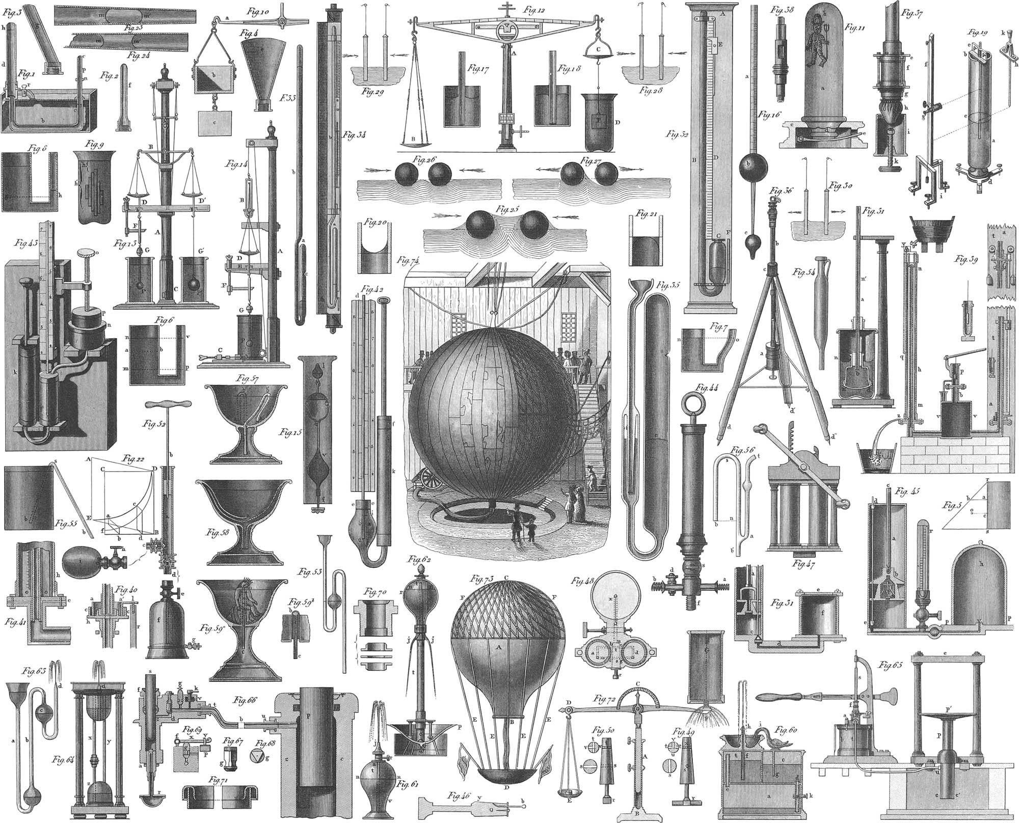
Pressure of Liquids
As the statics of solid bodies had reference to the laws of their equilibrium, hydrostatics embraces the theory of equilibrium in liquids, and of the pressure which they exert upon the walls of the containing vessel.
In liquid bodies, two forces are to be considered, namely, weight and molecular attraction; and these two forces may be readily imagined to be separated from each other, that is, a liquid may be supposed to exist without weight. Such a liquid left to itself would not fall: it thus needs no support on any side, and might even sustain a pressure and transmit it according to a certain principle. Hence the following axiom: a liquid transmits pressure acting upon any part of its surface, uniformly in every direction. Suppose a vessel to contain such a liquid, with a suitable piston, also without weight, placed upon its surface. The liquid would not flow out, even if the side of the vessel were pierced by an aperture. If, however, a weight be placed upon the piston, it would sink if not supported by the liquid, whose upper layer would likewise sink unless supported by the one beneath it, and so on to the bottom of the vessel. All these layers of liquid, therefore, receiving successively the same pressure, the result is the same as if the piston with its superincumbent weight pressed directly upon the bottom of the vessel. Hence it follows, that the pressure upon horizontal surfaces is transmitted from above to below without any loss, that is, is equal at every point, and proportional to the surface involved.
The same proposition holds good in reference to the walls of the vessel; for, supposing an aperture made in the side of the vessel by cutting out a piece equal in surface to the piston., the same weight as is placed upon the piston would be required upon this piece to prevent the liquid from escaping; and the resistance would be in proportion to the surface of the piece cut off. If the piston itself were pierced, the liquid would escape through it; liquids, therefore, transmit pressure uniformly in all directions. The laws thus developed for weightless liquids apply equally to those with weight, as it is here the single molecules which receive and transmit the pressure.
Another proposition with regard to liquids is the following: when a liquid is in equilibrium, its surface must be perpendicular to the direction of gravitation. When liquids are in equilibrium, they exert upon each other and all solid bodies with which they are in contact, a greater or less pressure: this pressure upon the bottom of a containing vessel being, without any regard to its shape, equal to the weight of a vertical column of the same liquid, which has the bottom of the vessel for its base, and the perpendicular height of the water for its altitude. Haldat’s apparatus (pl. 18, fig. 1) serves as an illustration of this law. It consists of a bent tube fastened in a box and so adjusted as to admit of attachments of various forms (figs. 2–4) being screwed on at one end instead of dh. Mercury is now poured into the tube, and the height, n, noted to which it rises in the arm c. The cylindrical vessel, d, is screwed on to the left hand and filled to a given height, h, with water, and the increased height, p, of the mercury observed in the other arm. The rise of the mercury is evidently the result of pressure exerted upon it by the water in d. Let off the water by means of the cock, r, and exchange the vessel, d, successively for figs. 2–4, filling them with water to the same height, the mercury will each time rise to the same height, p, although the amount of water in the different cases is very unequal.
The pressure experienced by any portion of the side of a vessel is represented by the weight of a column of liquid, whose horizontal base is equal to the area of the portion in question, and whose altitude is the depth of its centre of gravity below the surface of the liquid. Fig. 5 illustrates the pressure upon the different points of the vertical side of a vessel. Erect at any point, a, a perpendicular to rs, and make this equal to ar, or the depth of the liquid at this point below the surface, then ab represents the pressure experienced by the point, a; suppose similar perpendiculars erected all along rs, then the entire isosceles right-angled triangle thus produced, will represent the entire pressure exerted upon the side in question. If o be the centre of gravity of the triangle, then a line drawn horizontally from o will intersect the wall in a point, c, called the centre of pressure: its height above the bottom is one-third of the height of the surface of the liquid.
In vessels communicating with one another in any manner, figs. 6 and 7, for instance, the surfaces will stand at the same height, if the same liquid be contained in both vessels. Suppose in fig. 6 a horizontal partition to be passed through m, then, if F represent the area of this partition, and h the height pv, the pressure on the partition wall from below will be = Fh. In the broader vessel, if the height, am, at which the water is supposed to stand be represented by h′, the pressure upon F will be represented by Fh′. Suppose the partition wall now replaced by a layer of water, this will experience a pressure from above of Fh′, and a pressure from below of Fh; equilibrium can therefore only exist when h = h′, or when the level is equally high in both vessels. If the liquid in the different vessels be different, however, the level will be unequal. If, for example, in fig. 8, one vessel contain water and the other mercury, they will meet each other in the plane passing through g. Below the plane gh there is only mercury; above it in the one vessel there is water, in the other mercury, the water pressing upon the mercury so as to force it into the smaller vessel in proportion to its height, never, however, attaining to the same level. The heights of the liquids will naturally be inversely as their specific gravities, and as these are as 1 : 14, the column of water must be 14 times the height of that of mercury.
Law of Archimedes; Specific Gravity
Under certain circumstances, heavy bodies may move in a direction opposite to that of gravity. Thus wax and wood rise from the bottom to the top of a vessel filled with water; a piece of brass rises in mercury, &c. All these phenomena depend upon that important law first discovered by Archimedes, and named after him. A body immersed in a fluid loses in weight by an amount equal to the weight of the fluid displaced. This may be explained by means of fig. 9, pl. 18, where a combination of several vertical prisms is immersed in a fluid. The proposition is readily proved for a single right prism; as in this case the pressures on the different sides of the prism mutually balance each other, it is only necessary to consider that upon the top and bottom. The upper surface experiences a downward pressure equal to that of a column of fluid whose base is this upper surface, and whose altitude is the height of the fluid above the surface of the prism. The lower surface, on the other hand, is pressed upwards by a force equal to the column of fluid whose base is the lower base of the prism, and whose height is that of the fluid above this base, equal, therefore, to the height of the fluid above the prism, plus the height of the prism itself. The heights of these two columns differ, therefore, by the height of the prism, and it is therefore evident that the pressure from below, or the upward pressure, exceeds the pressure from above or the downward pressure, by the weight of a column of fluid equal in volume to the prism immersed. This excess of upward pressure acting contrary to the weight of the body, or to its gravitation, necessarily relieves the latter of an amount of weight equal to that of the fluid displaced. All bodies, of whatever irregularity of shape, may be considered as composed of right prisms, to each of which, and consequently to whose sum, the above reasoning will apply. A convincing proof of the accuracy of this law, which applies to both liquids and gases, may be had by means of the apparatus figured in fig. 10. At one end of a common balance is suspended a hollow cube of metal, beneath which is attached a solid cube, fitting exactly in the first one. Place the one in the other, and bring the balance to a state of equilibrium by loading the opposite scale with weights; suspend the solid cube beneath the hollow one, and allow the former to be immersed in the water, equilibrium will be disturbed, and the weight scale will sink; fill the hollow cube with water, and equilibrium will again be restored.
A perfectly homogeneous body floats in a fluid when its weight is equal to that of the fluid displaced, and it may then assume any position; if, however, its centre of gravity do not coincide with that of the fluid displaced, it only floats when the two centres lie in one and the same vertical line; the position, however, is fixed, only when the centre of gravity of the body is the lower of the two. Thus fishes float in water when they weigh as much as the water displaced; the equilibrium of their position, or the inferior situation of their belly, depends upon the air-bladder, and is so placed that the upper part of the fish is lighter than the lower. By means of the air-bladder, the fish can rise or sink in the water, floating at pleasure at any height, by its simple compression or expansion. As the fish cannot inspire air at pleasure, like an air-breathing animal, the bladder must contain a certain quantity of gas (consisting in most fishes of \(\frac{9}{10}\) oxygen and \(\frac{1}{10}\) nitrogen), which is compressed more by the muscles than by the surrounding fluid. This muscular compression is, of course, voluntary on the part of the fish, and the compression or expansion of the bladder stands in intimate connexion with it. The apparatus (pl. 18, fig. 11) known as the Cartesian Devils, illustrates this condition of things. The devil is a hollow glass figure, b, in which there is a very small opening, generally in the point of the tail. The figure is filled with water just enough to make it float in a vessel filled with water. Cover the vessel with a bladder, and place it inverted upon the stand, in which is placed a strong spring, e; then by the pressure of the spring, the air in the vessel is compressed, and the water driven into the inside of the figure, compressing the air already contained therein. The weight thus increased, the figure necessarily sinks to the bottom. Relax the pressure of the spring, and the air in the figure expanding again, forces out part of the water, thus allowing it to rise. Here the figure represents the bladder of the fish, and the pressure of the spring the muscular contractions exerted upon that organ. The gas in the bladders of fish, taken at a depth of about 3000 feet below the surface, sustains a pressure of almost 100 atmospheres. The expansion, when the fish rises to the top, is so great as sometimes to force the viscera out at the mouth.
The determination of the specific gravity of bodies is a very important application of the law of Archimedes. Various forms of apparatus have been devised for this purpose; a few only can here be mentioned.
The hydrostatic balance (pl. 18, fig. 12) used for this purpose, is a very accurate balance, such as is employed in chemical manipulation, and as will be described more fully under the head of chemistry. Any chemical balance may be employed for this purpose, by removing one scale-pan and substituting another, which, although of the same weight, is hung much shorter, and provided with a little hook beneath, from which the body whose specific gravity is to be ascertained, may be suspended. The absolute weight of the body thus suspended, is first to be ascertained by weighing it in the air, the weight being placed in the opposite scale. Place a vessel, D, filled with distilled water under C, and allow the body to be completely immersed in it, taking care to remove all air bubbles from its surface, its weight will of course be diminished, and to restore equilibrium, weights must be placed in C, or removed from D. The amount of these weights indicates the loss experienced by the body in its immersion, and consequently the weight of a mass of water equal in volume to that of the body itself. The specific gravity of the body is the quotient arising from dividing the absolute weight by the weight of an equal volume of water, or the loss of weight experienced when immersed in the water.
A very well adapted and useful hydrostatic balance is represented in pl. 18, fig. 13, giving a front view, and fig. 14, one from the side. To the main pillar, A, an arm is attached above, containing two pulleys, over which strings pass supporting a small beam to which the balance is suspended. The strings are united together into one behind the pulleys, and by means of the screw arrangement, C, may be drawn up or let down, the whole play amounting to 1–2 inches. The shears of the balance beam are pierced above, for the purpose of showing the point of the tongue, and thus determining whether equilibrium be attained or not. To the balance beam, B, are suspended the two scale-pans with small hooks beneath. DD′ is a thin plate attached to a special support beneath the scale-pans, admitting of being raised or depressed at pleasure. This plate, DD′, is pierced to allow passage to the brass wires attached to the hooks beneath the scale-pans. To the wire at D is attached a thin brass cylinder, pierced below, to allow anything to be suspended from it. This cylinder, about five inches long, is covered with paper, upon which an equally divided scale is drawn. In one corner of the plate,. DD′, a wire passes with considerable friction through an aperture; to its lower end the index, F, is attached, which, by the friction of the wire in the hole, can be placed at any desired position with reference to the scale. At the lower end of the scale cylinder is attached a weight, G, and to this, by means of a fine wire, the brass ball, P, of about \(\frac{1}{4}\)-inch in diameter. To D′ is suspended, by a horse-hair, the large hollow glass bulb, P′.
Suppose the weight, G, to be removed, and the wire with P attached directly to the cylinder; suppose P′ also to be replaced with a weight, z, heavy enough to produce an equilibrium with the other scale and its appendages, when the middle of the wire, with P attached, is intersected by the surface of the water. The wire to which P is attached must weigh exactly four grains to the inch. As brass is about eight times as heavy as water, the wire will lose half a grain for every inch immersed in the water. If. then, everything be in equilibrium when the centre of this wire lies on the surface of the water, and if the index, F, lie against the middle of the scale cylinder, divided into 100 equal parts, the weight of a body can be ascertained accurately to within \(\frac{1}{100}\)th of a grain. Thus, lay the body to be weighed upon the scale at D, and restore equilibrium, so that the difference shall be less than one grain. If the entire balance be raised or depressed, by means of the apparatus, C, until equilibrium is perfect, and if the index, F, point exactly to the middle of the scale cylinder, then the weights laid in D′ exactly represent that of the body in question. If, however, the index, F, point above or below the middle of the scale, as, for instance, to 36, then \(\frac{36}{100}\)ths of a grain are to be added to or subtracted from the weight already ascertained, as the case may be, to determine the absolute weight of the body in D. To determine the specific gravity, again attach the bulb or cup, P′, restore equilibrium, and then place the body to be examined in P′. The equilibrium again restored by weights placed in D′, and the indications of the index, F, will give the weight of the water displaced.
The specific gravity of solids may also be determined by means of Nicholson’s areometer (pl. 18, fig. 15), which, by an error of the engraver, is represented inverted, and consequently requires an inversion of the plate to bring it right again. A small heavy mass, as a glass ball, filled with mercury, is suspended to a hollow glass body, V, whose upper part on immersion must project above the surface of the liquid. To the upper part is attached a fine rod, f, which carries a small pan, c. Lay upon this the body to be examined, and cause it, by means of additional weights, if necessary, to sink to a point, f. Remove the body from the pan, and substitute as many weights as will bring the point p of the areometer back again to the surface of the water: these additional weights give the absolute weight of the body, equal, we will suppose, to n. Remove the weights, n (not, however, those previously imposed), and place the body in a little basket between V and I. The instrument will not sink to f, this requiring the addition of weights in the upper pan. The amount of these latter weights = m, will give the weight of the liquid displaced, and the specific gravity = \({\Large \frac{n}{m}}\).
To determine the specific gravity of fluids, a scale areometer (pl. 18, fig. 16), may be employed. This consists of a cylindrical glass tube, in the lower part of which a ball, b. is blown, which is continued into a smaller tube, terminating finally in another ball, c. This latter ball is filled with shot or mercury sufficiently to cause the instrument to sink vertically in distilled water to a certain point, the zero. In any other liquid the instrument will sink until its weight is equal to that of the liquid displaced; deeper, therefore, as the liquid is lighter : so that the specific gravity of the liquid can be ascertained by the depth of depression. For this purpose, the areometer of Gay Lussac has the point, a, at which it stands in water, indicated by 100, and upon the tube above and below this point, a divided scale attached, so that the volume of the tube included between any two divisions of the scale is \(\frac{1}{100}\)th volume sinking in the water, the numeration being carried from below upwards. An areometer divided in this manner is called a volumeter. The specific gravity of a liquid is ascertained by introducing the instrument and dividing 100 by the number on the scale to which it sinks. A volumeter of this character is the more sensitive as the distance between the divisions is greater in proportion to the thickness of the tube: to avoid making them of inconvenient length, they are not made to be of universal application, but for particular liquids, or for liquids that are lighter or heavier than water. The zero of volumeters intended for liquids lighter than water is placed at the lower end of the scale, that for those heavier than water at the upper part; and the filling of the ball, c, is to be adjusted so that the tube a may sink to the proper point. The scale, which for every good instrument must be made especially, is generally on a slip of paper placed inside of the tube, which is then hermetically sealed above it. There are other areometers, which, more conveniently, give the specific gravity directly: in these the scale is not equally graduated, but the divisions increase from below upwards. For practical purposes, such areometers are much used for particular liquids, as alcohol, solutions of salt, milk, &c., giving the proportions in which they are mixed with other substances. They receive particular names, according to the fluid for which they are destined: Alcoholmeter, Saccharometer, Lactometer, Hydrometer, Salometer, &c.
Attraction between Solids and Liquids
If the extremity of a fine tube be immersed in a liquid, the level of the latter will be higher or lower inside the tube than outside of it, according as the tube is moistened by the liquid or not; thus, in a glass tube immersed in water, it will be higher (pl. 18, fig. 17), and immersed in mercury it will be lower (fig. 18). The force which causes these phenomena of elevation or depression is called capillarity, or capillary attraction, and comes into play whenever solids and fluids are brought into contact. In such cases, the heights of elevation or depression of the liquid are inversely as the diameters of the tubes; the finer these are, therefore, the higher is the rise or fall of the liquid. For the empirical determination of this law, a very accurate direct measurement of the place of the liquid in the tube becomes necessary; and for this, the apparatus invented by Gay Lussac answers very well. In this, apparatus (fig. 19), the height of the liquid in the tube can be ascertained by means of a small telescope, g, moved up and down a graduated post, and capable of being fixed at any elevation. Having fixed the post of the telescope in a vertical position by means of the adjusting screws and the plummet f, the height of the liquid in the tube is to be noted, the tube then moved aside, and the plate h, through which passes with some friction a finely-pointed rod, k, laid upon the vessel a. The point of this rod is to be brought in exact contact with the surface of the liquid, and the height read off by means of the telescope. The difference of these heights will be the height of the column of liquid in the interior of the tube.
It must not be forgotten that whenever a liquid rises or falls in a narrow tube, the summit of the column is not perfectly flat, but concave in the first case, as in fig. 20, and convex in the second (fig. 21), the radius of convexity and concavity being equal to the inner diameter of the tube. The regularity of this structure, however, depends entirely upon the cleanness of the inside of the tube.
If a capillary tube which has been employed in any of the above-mentioned experiments be raised out of the liquid, the liquid originally contained therein will be retained there by the pressure of the atmosphere, and a drop which may have been suspended to the lower end will even be driven inside; and with sufficiently thin walls, the height of the column of liquid may thereby be raised to nearly double the original amount. Syphon tubes exhibit similar phenomena; and in concentric tubes the phenomena of capillarity take place in the inner tube and the ring between the two, as if each one alone were present. If, therefore, the diameter of the tube be twice as great as the thickness of the tube, the summits of the columns will be equally high in both. Parallel plane plates may be considered as parts of infinitely great concentric tubes, and experiment has shown that the phenomena of capillarity are precisely the same in the two cases. If the plates are inclined at a very acute angle, as in pl. 18, fig. 22, ADBE and CDBF, the liquid in the narrow part will rise higher than in the wider, and in such proportion, that the areas of the rectangular transverse sections, as ab and cd, are always equivalent. The shape of the curve, DE, forming the outline of the fluid, is that of an equilateral hyperbola, whose asymptotes, on the one hand, represent the line of intersection of the plates, and on the other, the level of the liquid. If the plates be removed from a vertical position to a horizontal, and a drop of water be interposed, it assumes a circular form, and passes to the line of intersection of the plates, and this with a rapidity greater in proportion to the sine of the included angle. Similar phenomena are exhibited by conical tubes. The small column of liquid, mm′, moves towards the point of the tube, as in fig. 23, and towards the broad end, as in fig. 24, and in the two cases assumes either a convex or a concave outline.
As a general rule, solid bodies cannot come in contact with fluid without the surface of the latter experiencing a greater or less change. Particularly remarkable in this respect are the phenomena of attraction and repulsion presented by bodies swimming in liquid. Two balls swimming in liquid and moistened by it, as balls of cork in water, when within sufficient proximity, attract each other with considerable intensity (fig. 25); likewise, two balls not moistened, as of wax (fig. 26). On the other hand, two balls repel each other when one is moistened and the other not (fig. 27). Similar phenomena are presented by vertical plates (figs. 28 to 30).
Another of the phenomena of attraction is the adhesion of plates to the surface of water, so that when they lie horizontally upon this surface, they can only be raised by the exertion of a greater or less force. The amount of this force is dependent upon the density of the fluid, increasing with this density. The material of the plate produces no difference in the result.
We cannot here go into an elucidation of the theory of capillarity, but will only remark that, according to the most recent theory of Mile, capillarity is nothing else than a mechanical molecular activity, which produces the drop and the bubble—the negative drop—and which is modified by the influence of the narrow space and of the adhesion.
Endosmosis
It is well known that a concentrated aqueous solution of any substance may be diluted with perfect uniformity throughout; if, however, there be no immediate contact between the water and the solution, but the two be separated by a porous partition with very fine pores, the liquid must pass through these pores to become mixed together. It may very often happen, however, that this partition admits of a more ready passage to one liquid than to the other, and the levels of the two, in their respective compartments, will then be different. Filling, for instance, a glass cylinder closed at the bottom by a bladder, with a concentrated solution of blue vitriol (sulphate of copper), and placing this in a vessel of water, the water will pass through to mix with the solution; the elevation of the liquid in the inner cylinder consequently rises, that in the outer vessel falling. If the inner cylinder be the one filled with water, the reverse will be the case, a depression here ensuing instead of an elevation. These phenomena investigated by Dutrochet, and by him named endosmosis and exosmosis, are exhibited sensibly in the apparatus figured in pl. 18, fig. 31, and by its inventor, Dutrochet, called endosmometer. The glass vessel, b is closed inferiorly by a piece of membrane or bladder, cd, and filled to a certain height with alcohol, the upper end stopped by a cork in which a glass tube, a, is fixed air-tight. This apparatus is placed in a larger vessel filled with water, and likewise closed by a cork, through which passes the tube, a. If the surface of water in the latter stand, say at n, equilibrium soon takes place, the surface of the alcohol standing perhaps at n′. Endosmosis now commences, the water penetrates the bladder against the resistance of the alcohol, and the alcohol column rises above n′, finally running out of the open end of the tube. If the experiment be reversed, so that the water shall occupy the place of the alcohol in the smaller vessel, the level will fall in the latter, owing to an ensuing exosmosis. Both operations continue until the liquids on each side of the membrane are homogeneous, and the difference of level is simply the result of the pores of the membrane being too minute to permit the action of hydrostatic pressure: for, if this membrane be moistened even. on the side opposite to the liquid, no drops are found. Endosmosis and exosmosis play a great part in the organic world, since absorption and the distribution of the nutritious juices are almost entirely results of these operations.
Dynamics of Liquids; Hydrodynamics; Hydraulics
Velocity of Efflux
Hydrodynamics exhibits the laws of motion of liquid bodies; and at the head of this part of natural philosophy stands the law of Torricelli, that when an aperture is made in the side or bottom of a vessel filled with liquid, this liquid escapes with a velocity equal to that which would be attained by a body falling freely from the surface of the liquid to the orifice of discharge. According to this, the velocity of efflux is entirely independent of the nature and specific gravity of the liquid; it is in connexion, however, with the depth of the orifice below the surface, and is as the square root of the height of pressure. A convenient form of apparatus for experiments upon the efflux of liquids is represented in pl. 17, figs. 32, 33. The main part consists of a cylindrical tin vessel, communicating with a glass tube, in which the liquid stands at the same height as in the vessel itself; this height is measured by a scale attached to the tube. In the side of the vessel are two apertures, b and c, one above the other; there is a third opening in the bottom of the vessel, on which account the small table supporting it must have a hole pierced through it; a fourth orifice is to be found at a, in a short horizontal tube. This latter part is represented on a larger scale in fig. 33. Through the wall of the vessel, aa, passes a tube, d, which ends in a shoulder. In this tube is a second smaller one, capable of rotation about its axis, within the first. In the side of this smaller tube is a thin plate of brass, with the efflux aperture screwed in it, and by turning the tube this aperture may be directed vertically up or down, sideways or obliquely. By means of the valve, c, the access of water to the aperture, b, can be regulated at pleasure, the other apertures having also valves raised by strings when the water is to flow out through them.
To prove the Torricellian law by experiment, suppose the water to pour out of the point a, in fig. 32, with the same velocity as if it had fallen from the surface of the water to the depth a, then the stream of water must again attain the same height. This, however, is by no means the case, as the water falling from the highest point of the column retards the ascent of that following after it, as is shown by the fact that the stream ascends considerably higher when its direction is so inclined as to prevent this interference. Under favorable circumstances an altitude can be obtained equal to nine tenths of the depth of fall; the remaining tenth is accounted for by the resistance of the atmosphere and the friction of the sides of the tube. Allow the water to pass out from b or c (fig. 32), and the stream will be as represented in fig. 31: it will form a parabola whose shape depends upon the velocity of efflux. The theoretical parabola will, however, differ from the actual, in the ordinate being less than that of calculation, the reason lying in the retardations of atmospheric pressure and of friction.
The stream of water, immediately after leaving the orifice, contracts to two thirds of its diameter, this contraction continuing, although in an insensible degree. In streams directed upwards, the jet expands continually after it has reached its greatest contraction of two thirds of its diameter, at a distance from the orifice equal to its diameter. The stream retains its constant form during only a certain part of its length; then it is separated into greater or smaller currents, which assume very various forms according to the shape of the orifice of efflux.
Should the efflux take place not through a thin plate but through a tube, considerable changes take place if the tube have not the shape of the compressed stream of water. Cylindrical escape pipes do not produce any difference under great pressure; at a less pressure, however, they increase the discharge, this taking place to a still greater extent in conical pipes: in all these cases, however, the velocity of efflux is diminished.
The Swimmer of Prony (fig. 35) is an apparatus employed for obtaining a constant height of pressure of water. C is a box floating in the vessel, D, and supporting, by means of the rods A, B, a second box, G (below the aperture, E, of the vessel, D), into which all the water flowing from D is received through the funnel, F. The height of pressure in D will thereby remain unchanged, as the weight of the box, G, increased at the rate of the efflux from D, will draw down the box, C, so as to replace the water which has passed into G.
Lateral Pressure
Pl. 17, fig. 30, illustrates the laws of the lateral pressure of moving liquids. If water flow from a vessel, A, through tubes, their sides will experience no pressure if there is no friction to overcome, but by this a considerable part of the hydrostatic pressure is lost, and acts upon the walls of the tube. The narrower the tube, the greater is the friction, and so much less the velocity of efflux. The pressure which the walls of a tube, cf, have to experience, will be less the nearer to the aperture of efflux, f; making then an aperture at c, and erecting in it a vertical tube, the water will ascend to a height, cb, corresponding to the pressure on the walls of the tube at this point. Midway between c and f, at e, the pressure on the walls is only half as great; the water would therefore rise only half as high as at c, namely, to d; and placing in any other part, between c and f, a vertical tube, the level of the water would lie in the straight line, bf.
To measure the pressure of falling water, the apparatus represented in pl. 18, fig. 72, may be employed. Upon the foot, B, stands a cylinder in which the post A may be fixed at different heights. DF is a balance beam, whose horizontal position may be determined by the index on the graduated arc C. At E hangs a common scale-pan, and at F is a plate whose size equals that of the efflux orifice of the vessel G. Letting a stream of water fall upon F, it will press downwards upon this plate, and the horizontal position of the beam is to be restored by weights placed in E. These weights will represent the pressure of the water.
Reaction of Impact and Water
If a vessel be filled with water, without an aperture in any part of it, everything will be in equilibrium; if, however, in any part of the vessel an opening be made and efflux allowed, the pressure ceases at this point, and is consequently less than on the part of the vessel diametrically opposite: the vessel, then, if allowed, would move in a direction diametrically opposite to that of efflux. Upon this principle depends the efficacy of Segner’s water wheel. This consists of a vessel capable of turning about a vertical axis, at whose foot is a horizontal tube, bent in opposite directions at the two extremities, and in the same horizontal plane. The water escaping through these extremities produces a rapid rotation by the reaction of pressure on the sides of the tube opposite the opening; provided, however, that the pressure be sufficient to overcome the friction.
If a stream of water be directed against a movable body, it will cause a change in its position; and the force with which this is done will be in proportion to the amount of pressure. If, during the unit of time, as one second, a stream of water, whose height is M, fall from a height, h, Mh will be the momentum of this column of water; and the force obtained by the impact of the water may be easily calculated.
The most important application of the impact of water is to be found in water wheels used for the propulsion of machinery. The most usual water wheels are vertical, with a horizontal axis. They are divided, according to the point of application of the force, into overshot, in which the water falls into the buckets of the wheels, from above and beyond the highest point; undershot, in which the water strikes against the lower float boards; and middleshot, or a medium between the other two. In the ordinary water wheels a good deal of power is lost; Poncelet has therefore constructed wheels with curved floats, which are much more powerful. Most powerful of all, however, are the so-called top-wheels, or turbines, invented by Fourneyron. In these the wheel is horizontal and the floats vertical; the water is carried through peculiarly constructed conducting curves against the floats, and turns the wheel around like a top, with such force indeed that 75–80 per cent, of the force of water employed is effective. In the division of the work specially devoted to Technology and Machinery, reference will again be made to the technical application of water power; where also the construction of the water-column machine will be explained—a machine in which the pressure of the water acts upon the piston of a pump, producing a backward and forward motion, which can be transmitted by proper connexions to other machinery. We may mention, in conclusion, another hydraulic machine, which can be employed to great advantage in many cases: this is the hydraulic ram, invented by Montgolfier in 1797, and employed in raising water. In pl. 17, fig. 36, mm is a horizontal tube, in which the water flowing from a reservoir moves with a velocity dependent upon the height of pressure. At k is a valve closed by the velocity of the escaping water; by it the aperture at this place may be closed. The water now pressing through the tube i into the cast iron reservoir d, enters, after raising another valve, into a great cast iron receiver (the air-vessel), and in this manner reaches the ascent tube, ca. Into this it is driven with a much greater force than would be produced by the height of pressure alone, as by the closing of the first valve, which suddenly obstructs the motion of the water escaping there, a pressure is produced upon the sides of the tube. In the ascending tube, the water rises to the height allowed by the elasticity of the air in the air-vessel, and the pressure of the water already raised; then the valve leading to the air-vessel again closes; the conical valve first mentioned falls by its own weight; the water commences again to escape through it, and the play of the valves, or the butting of the ram, begins afresh.
Statics of Aeriform Bodies, or Gases.—Aerostatics
Gaseous or aeriform bodies, among which the atmospheric air occupies the most important place, in some respects form a great contrast to the true liquids. At an earlier period, atmospheric air was considered as a simple body—an element; at the present day, however, its component parts are well known, and its place among compound bodies ascertained. It shares with the other gases, as well as with solid and liquid bodies, the same general peculiarities, and is also subject to the influence of gravitation and of molecular forces.
Atmospheric air surrounds the globe on all sides, having a thickness of from 30 to 35 miles; it is the cause of a great number of phenomena, some of which will here be referred to, others belonging to the subject of meteorology.
That the air had weight was known to Aristotle; Galileo, however, and, after him, Torricelli, were the first to prove this by experiment. Exhausting the air from a hollow globe, suspending this to the end of a balance brought into equilibrium by means of weights, and afterwards allowing the air to enter the globe, it will be found that equilibrium is again destroyed, and must be restored by the imposition of more weights : their amount will express the weight of the air contained.
The molecular force acts in gaseous bodies very differently from what it does in the case of liquids and solids, endeavoring to separate the molecules one from another, this influence being called elasticity or tension of gases. Of the activity of this force we may be convinced by introducing a well-closed bladder under the receiver of an air-pump. When a vacuum is produced, the contained air expands the bladder as exhaustion proceeds. The expansive force of air is unlimited, as in a state of greatest expansion it still exerts a pressure upon the containing walls. For this reason gases can have no free surface like solids and liquids, as they would extend inimitably into space; there is, therefore, for them only one condition of equilibrium, namely, that the elasticity in one and the same layer is equal. For equilibrium, therefore, the lower layers must constantly remain the densest; for which reason the pressure of the atmosphere must be greater at the level of the sea than on the tops of mountains. It must not be understood, however, from what has already been said, that as the air can have no free surface, the assumption of a limit of the atmosphere to some miles is erroneous. This rests upon grounds hereafter to be stated.
The atmospheric pressure may be measured; and to its existence innumerable phenomena testify. Immerse the lower end of an open tube into water, the fluid will rise into it, according to the laws of hydrostatics, to an equal height with that surrounding it; suck some of the air from the tube, and additional water will enter, because the equilibrium of atmospheric pressure is disturbed. The air within becomes rarer and lighter; the external atmosphere, therefore, pressing upon the external surface of the water, forces it up into the tube until the air therein contained is compressed sufficiently to exert the same pressure with the outer, or, in other words, until the weight of the water raised is equal to the excess of external pressure. Exhaust the air entirely from the inside of the tube, and the water must rise until the weight of the column raised is equal to the weight of a column of air having the same base, and a height equal to that of the atmosphere. It has been found that a column of about 33 feet is the maximum that can be raised in this manner. Torricelli from these facts established the following conclusion: for two different columns of fluids to be in equilibrium, they must be to each other inversely as their densities. Mercury is fourteen times heavier than water; if, now. the pressure of the atmosphere sustain a column of water 33 feet in height, it will sustain one of mercury ff feet, or about 29 inches. That this is actually the case is shown by a simple apparatus for measuring the pressure of the air, termed the Barometer, consisting essentially of a glass tube about 31 inches long, closed at one end and filled with mercury. After filling this tube, hold the finger on the open end, and inverting it in a basin of mercury, remove the finger. The height of the mercurial column remaining in the tube, which in places at a slight elevation above the sea amounts to a mean height of about 28.6 inches, serves as a measure of the pressure of the air, as this, acting on the external surface of the mercury in the basin, sustains that in the tube. Along the top of the mercurial column, a scale divided into inches and fractions of an inch is attached, sometimes on metal, sometimes on paper, and occasionally upon the tube itself. To ascertain the amount of atmospheric pressure upon any given surface, calculate the weight of a column of mercury whose base is that of the given surface, and whose height is that of the mercury in the barometer.
Many different constructions of the barometer have been made, principally reducible, however, to two kinds, cistern and syphon barometers. The common barometer (pl. 18, fig. 32) is one of the first kind. It consists of a long tube, B, curved beneath and dipping into the vessel or cistern, C, upon which the pressure of the external air can act, as it is open. The whole is fastened to a board, A, and a scale, D, with a movable index, E, attached, to mark the variations of pressure by the rise or fall of the mercury. This scale is generally divided into inches, and tenths or twelfths, and a vernier frequently attached to the index for measuring very slight variations. The small scale, F, serves to measure the mercury in the vessel or cistern. Attention must always be directed to the vertex of the convexity of the mercury, which is formed in the ascent. In filling the barometer, care must be taken that there are no bubbles of air in the mercury, or attached to the tube, these being driven out by boiling the mercury in the tube. If these are not expelled they will rise into the top of the tube, and exert atmospheric pressure upon the top of the mercurial column, thus neutralizing in some measure the external pressure, and causing the mercury to stand at too low a point; this undue depression will be increased, also, whenever expansion of the included air is produced by an increase of temperature. The empty space above the mercurial column of every barometer is called the Torricellian vacuum. The simplest barometers have only a straight tube, dipping directly into a separate vessel of mercury.
Since the barometer has been applied to the measurement of heights, the older construction for this purpose has been changed, and the syphon barometer (fig. 33) employed. This also consists of the tube, b, bent into a syphon shape at a, and closed at both ends. The short limb has at c a capillary opening which admits the entrance of air. but not the exit of mercury, so that the tube may be inverted without the contents escaping. To prevent the entrance of air into the larger limb during this inversion, Bunten has invented the construction represented in fig. 35. Here the mercury on inversion enters the space, d, so that the point of the downward projecting tube is, during inversion, constantly closed air-tight by the superincumbent mercury. It will readily be understood that in the figure only the lower part of the barometer is represented. In the syphon barometer, the quicksilver surface exposed to the pressure of the atmosphere has no fixed position, and the zero of the scale must therefore be brought to the place of the inferior surface.
In the barometer of Gay Lussac (fig. 34), the long limb, b, is bent in such a manner, that its upper part and the short limb, a, lie in the same straight line; the stations of the two surfaces can therefore be read off on the same scale, and then the zero is in the centre, so that the reading is of how much one scale is above, and how much the other is below; the sum is then the proper height of the barometer. This double observation is necessary on account of the influence of temperature upon the mercury.
The barometer of Fortin (figs. 36–38) is a cistern barometer, and has the advantage over others, that the mercury in the cistern, a, has an invariable level. The bottom of the cistern is formed by a leather pouch, h (fig. 37), against which a screw, k, presses, by which the surface of the mercury may be elevated or depressed. If then g be screwed fast to i, the surface of the mercury in the cistern must correspond exactly with the zero of the scale, which is at the extremity of a fine point. When the image of this point in the surface of the mercury is made to coincide with the point itself, the adjustment is made. The barometer is surrounded by a metallic tube, in whose upper part there are two opposite slits for observing the top of the mercury. The scale is attached to the metal tube. To assist the eye in determining the exact height of the mercury, there is a slider on the metal tube, which has also two slits corresponding to those of the tube, only a little broader. The slider is so adjusted that the upper edges of its slits coincide exactly with the top of the mercurial column.
Experiments and calculations instituted for the purpose, assign to a station of the barometer of 28.6 inches, an atmospheric pressure of about 14.6 pounds upon the square inch, which, upon a surface equal to that of the human body, amounts to from 30,000 to 40,000 pounds. This at first appears incredible, as it seems impossible to resist so enormous a pressure; the matter becomes more intelligible, however, when it is considered that the pressure acts on all parts, both inside and out, at the same time, so that the pressure from one direction is exactly neutralized by that from the other. This weight then is only sensible when the equilibrium is disturbed, as in a violent wind, &c. The compression or crushing of the body is resisted by the penetration of the external air into all the cavities of the body by means of innumerable fine pores as well as of larger passages, so that both inside and out, air is present in the same state of tension. This atmospheric pressure is of the greatest importance to the animal organism, as will be made evident by a single example. It is known that the head of the thigh bone consists of a ball playing in a socket of the pelvis inclosed in a capsular ligament, and possessing motion in almost every direction. If the leg be unsupported, and even if all the muscles and tendons be severed, the head of the thigh bone does not fall out of its place. If, however, the capsular ligament be pierced, or communication be made in any other way with the external air, the thigh immediately descends out of its place. It is thus evident that the pressure of the air upon this air-tight joint must play a great part in keeping it in position. In this manner may be explained the peculiar sensation of weakness and relaxation experienced at great elevations on mountains; the diminished pressure of the air takes from the whole frame its compact and well knit character.
One of the most important propositions in the theory of equilibrium of gaseous bodies, is the law discovered by Mariotte, and called after him Mariotte’s law: that the volume of a gas is inversely as the pressure to which it is subjected. Thus twice the pressure is required to reduce a gas to half the volume, &c. Arago and Dulong have shown the accuracy of this law up to a pressure of 27 atmospheres, or a pressure 27 times that of one atmosphere. For this purpose they employed the apparatus represented in pl. 18, fig. 39. In the middle of an old tower, a mast, a, of about 100 feet in height, was erected, to which a long glass tube, t, was attached, composed of 13 single tubes of six feet in length. At the foot of the mast was a cast iron vessel, v, filled with mercury, with a forcing pump, p, attached at b, and provided with a manometer tube, mn, closed above, graduated, and filled with dry air. When the mercury stood at an equal height in the tubes, t and mn, the air in the latter, of known volume, experienced the ordinary pressure or that of one atmosphere. Forcing water, however, by means of the forcing pump, into the upper part of the vessel, v, the air in the tube, mn, would become compressed, and the mercury rise in the tube, t. The scale on the first tube gave the volume of the included air; the difference of height of mercury in the two tubes gave the corresponding pressure. Fig. 40 represents the manner in which the single parts of the vertical glass tube were united by strong rings, aa′; c is an upward projecting rim, filled with melted cement, to render any escape of mercury impossible. Fig. 41 shows how the manometer tube, mn, was fastened to the plate, c, of the cast iron vessel, by means of the shoulder, h. The apparatus, qy (fig. 39), served to move along the vernier of the manometer, which was inclosed in a glass tube.
It has been mentioned above that the barometer was applicable to the measurement of heights, as the atmosphere in its lower strata exercises a greater pressure than in the upper, and that consequently the height of the barometer would be greater in one case than in the other. These measurements would be very simple if the air were not elastic, or at least very slightly compressible; for then, by obtaining a point of departure or unity by direct measurement of one height, other altitudes could be readily calculated. This, however, is impossible, as the less the pressure upon a layer of air, the less is its density; or in other words, the greater the ascent, the greater the rarity of the air. Mariotte’s law renders it possible, however, to attain to accurate results. Suppose the height of the barometer at a certain elevation to be 760 millimetres, and by ascending 11.5 millimetres, the height of the mercury to be only 759 millimetres = \(760\Big({\Large \frac{759}{760}}\Big)\). Taking 11.5 metres as unity—then as the density of the air is proportional to its pressure, the next layer will be less dense, and, indeed, only \({\Large \frac{759}{760}}\) as dense as the one below it; the height of the barometer then is there only \(760\Big({\Large \frac{759}{760}}\times{\Large \frac{759}{760}}\Big)=760\Big({\Large \frac{759}{760}}\Big)^2\), and so on, so that for n × 11.5metres, the height of the barometer is \(760\Big({\Large \frac{759}{760}}\Big)^n\). If now B be the height of the barometer at a, and B′ that at a place, b, higher than a by unity, and the quotient, \({\Large \frac{\mathrm{B}'}{\mathrm{B}}}=q\), then, according to the preceding considerations, the height of the barometer for a place, b, higher by m units, will be =Bqm, and m can be obtained from this equation. Thus \(q^m={\Large \frac{b}{\mathrm{B}}}\), and \(m=\sqrt[q]{{\Large \frac{b}{\mathrm{B}}}}\). Here, however, must be taken into account the temperature and the vapors present in the atmosphere; the consideration of the corrections necessary on this account would carry us too far beyond our limits.
For determining altitudes where the greatest possible accuracy is not required, the easily transportable Differential Barometer of Kopp (pl. 18, fig. 42), may be employed to advantage. It consists of a straight cylindrical glass tube, k, united by means of a narrow tube with a glass vessel, i, closed tight above, through whose upper cap a thinner tube, cd, passes. In the tube, k, is a leather piston, which may be moved up and down. The instrument is filled with mercury, so that when the piston, f, is raised, in consequence of the atmospheric pressure, almost all the mercury passes from i into k and the air contained in the vessel, i, communicates with the external atmosphere. A scale is attached to the tube, cd. Depressing the piston, the mercury is again forced into i, and there confines, as it closes the lower end of the tube, cd, a certain quantity of air of the same density as that external to it. Continuing this depression until the mercury touches a point attached, similar to that described in the barometer of Fortin, the inclosed air becomes condensed, in a proportion dependent upon the dimensions of the instrument and the position of this point. If, for instance, the air were condensed to three fourths its original volume, the height of the mercury according to Mariotte’s law, would be one third of the actual height of the barometer, and for this proportion, as well as any other, the actual height of the barometer would be obtained by multiplication into a factor developed from the construction of the instrument. If now there be another point in the instrument, standing somewhat deeper or lower than the first, it can be brought in contact with the mercury by a change in the position of the piston, where then the factor would of course be different. Making observations in immediate succession, and at the same place, with the two points, the products of multiplication by the different factors must be equal; the two points therefore control each other. There must, of course, be attached to the tube, cd, as shown in the figure, two different scales for the two points.
Upon the law of Mariotte depends an apparatus termed volumeter (fig. 93), invented also by Kopp, for determining the volume of powders. The tubes, k and i, correspond to those of the same name in the differential barometer, being likewise filled with mercury; from i passes a bent tube to the wide glass cylinder, n, whose upper broader end is carefully ground off for the purpose of placing a plate of glass upon it, and rendering it air-tight by the addition of a little tallow. Closing the cylinder, n, and depressing the piston, k, until the mercury touches the lower end of the ascending tube, a certain quantity of air will be inclosed in l and n: pressing down the mercury to the point, a, the included air will be compressed, a corresponding column of mercury rising in the ascending tube. If, before laying on the glass plate, any body had been placed in the cylinder, n, then the mercury standing at c, less air would be included than before, and in forcing the mercury up to a, it would be more compressed, so that the ascending tube would contain a greater column of mercury than before. From the height of this column of mercury the volume of the body contained in the cylinder is to be calculated. The powder to be examined is introduced in a platinum vessel, of about the shape of n, and nearly the same size. The volume of air included when the empty vessel alone stands in n, suppose it to be 15.07 cubic centimetres; and also the volume between c and b, say 2.5 cubic centimetres, to which the air is compressed, must be known. Now introduce the body whose volume is to be determined into n, and depress the piston again from its highest position, where c is closed by the mercury; a quantity of air, x, is inclosed, and when the mercury comes in contact with the point a, the air is compressed to x—2.5. Let the column of mercury last obtained = 90 lines, and the actual height of the barometer = 336 lines, then the compressed air now experiences a pressure of 336 + 90 = 426 lines, and 426 : 336 :: x : x—2.5; x, therefore, = 11.72. As now, when n is empty, the volume included = 15.07 cubic centimetres, the volume of the body examined will be = 15.07 − 11.72 = 3.35 cubic centimetres.
Next to the barometer comes the air-pump, invented by Otto von Guericke, one of the most important instruments for elucidating the properties of the air. It serves to produce by successive rarefaction as complete a vacuum as possible, although this can never become so perfect as the Torricellian vacuum. Imagine a cylinder in which a piston moves air-tight, and closed below, then on raising the piston a vacuum will be produced. If, now, the cylinder be united with another inclosed space by a tube, so that the air can pass from the latter into the former, then, on raising the piston, the air would make this transit, but on depressing the piston it would return again. Suppose, however, a cock to be placed in the tube, by means of which the return of the air can be prevented, while its egress is allowed; then by the alternating action of the piston and turning of the cock, the air in the vessel may be reduced to a minimum, even if a perfect vacuum may not be attainable on account of the infinite expansion of air. This is the simplest construction of the air-pump; it has, however, since its invention, received various modifications and improvements.
Pl. 18, fig. 44, represents a small hand air-pump, according to the construction of Gay Lussac. The main part consists of a hollow cylinder or tube of brass, in which an air-tight piston plays up and down. In the latter is a valve opening upwards; thus shut during the ascent of the piston, and open during its depression. At b is attached the receiver, the vessel in which the vacuum is to be made, consisting generally of a plate and glass bell. The screws a and f serve to screw the air-pump to a table or board; at d a cock is attached, as also at s. If, now, the latter cock be opened and the former closed, and the piston elevated, a part of the air in the receiver will pass out through the first horizontal and then vertical canal, ab, into the cylinder, and the air in the receiver will become rarefied. Depress the piston after closing the cock s, and the air under the piston passes out through it by means of the valve in the piston head. To let the air again into the receiver, the cock at d must be opened.
A sectional view of a larger air-pump is shown in fig. 45, pl. 18. Here a is the cylinder, in which works the air-tight piston, b, which contains a valve opening upwards, and is moved by the piston rod, c. The rod ed opens and closes the valve for the cylinder; at its lower end is a truncated cone, e, fitting in a conical opening. At h is seen the glass bell to be exhausted, whose edge must be ground perfectly plane, in order that it may fit air-tight upon the ground plane, pp. In the centre of this plate is a female screw, v, for screwing on any other form of receiver; and from this goes a canal to the conical opening at e. If, now, the piston resting on the bottom of the cylinder be elevated, the valve at e opens until the shoulder at d strikes against the upper plate of the cylinder, and the air in part rushes from the receiver into the cylinder: on depressing the piston, the valve at e is closed, and the air in the cylinder escapes through the valve in the piston. At r is the barometer gauge, or contracted barometer, inclosed in a long narrow bell, and in communication with the air in the receiver by means of the canal ev. The mercury at first completely fills the one leg of the bent barometer tube, but after a considerable rarefaction, begins to sink, and the difference of height of the two mercurial surfaces gives the pressure of the air in the receiver. If, for example, this difference amount to one inch, at a barometrical height of 28 inches, the air in the receiver will be rarefied 28 times. Fig. 46 represents a double-acting cock, y, in the canal between the receiver and cylinder, that is, a cock bored through in two directions: the one aperture is straight, and during exhaustion unites the receiver and cylinder; the other is bent into a knee, and opens into a lateral opening, which, during exhaustion, is closed by a metal stopper, b. To admit air into the receiver after exhaustion, the stopper must be extracted and the cock turned in such a manner that the air can penetrate into the receiver through the side aperture.
Air-pumps are divided into cock and valve pumps, and moreover into one and two-cylindered. Fig. 47 represents an air-pump provided with two cylinders. Here the two piston rods are toothed, and a piston interposed in such a manner that by the motion of a handle they can be alternately elevated and depressed, the one ascending, the other descending at any given time. In this manner the exhaustion goes on uninterruptedly, and is completed in much shorter time.
In the common air-pumps, however well they may be constructed, there is always a space intervening between the piston and its point of greatest depression and the bottom of the cylinder, which can never be exhausted. The air in it obstructs the rarefaction of air in the receiver, and sooner or later puts a stop to it. To obviate this difficulty, Babinet has constructed a cock of peculiar form, represented in figs. 48–50. In fig. 48, a and d are the two cylinders of a double cylinder air-pump, and r the cock attached between the two cylinders, a little below their base. This cock has four openings (figs. 49 and 50). The first and second, s and t, pass completely through and are perpendicular to each other; the third, v, is parallel to s, going, however, only to the centre of the cock, and opens in t. The same is the case with the fourth opening, u, which runs parallel to the longitudinal axis of the cock. From the bottom of the two cylinders pass curved canals which terminate at b and e in the openings of the cock. At first, the cock is fixed in such a manner that the opening, t, unites both canals; and this position, in which it exerts no particular influence, is continued until the mercury will fall no longer in the gauge. The cock is now slightly turned, so that the bore, s, unites the two cylinders; and at the same time the opening v unites the cylinder a with the receiver. If the piston in a be depressed, the rarefied air beneath it is driven over into the other cylinder; when, however, the piston in d is depressed, the valve in the bottom of d is closed, and in the cylinder a the space above mentioned contains only rarefied air, so that the rarefaction in a is much greater than before. It is only after repeated strokes of the pistons that a new limit to rarefaction is attained.
The condensing pump (fig. 51) serves to condense the air, and differs from the air-pump merely in having the valves to open and shut in a different direction. In depression the piston drives the air into the receiver and compresses it; in elevation the external air opens the piston valve and presses into the tube, while the air in the receiver is retained by the valve in the bottom. The receiver must be screwed down, else it will be forced up by the compressed air. Many condensing pumps are so arranged as to be applicable to various apparatus or receivers in which the air is to be condensed. One of this kind is represented in fig. 52. It consists of a tube or cylinder, and a piston, b, without a valve. The receivers are screwed on to the lower end of the tube, either at c or d; a valve then attached admits only the ingress, not the egress of air. The receivers f and i may be closed when necessary by the cocks, e, h, and g. For admitting successive portions of air into the cylinder or tube, a lateral opening in the tube, or, as in the figure, a lateral valve, may be used. The latter serves principally when a gas, not atmospheric air, is to be condensed.
The air-pump, in its application, is confined not merely to physical experiment, but is of the highest importance in the arts. It is there employed on the one hand for rarefying the air, as in the steam engine and sugar manufacture, and on the other for condensing air, as in driving of machines by condensed air, in the air-gun, &c. In the air-gun the air-vessel in which the condensed air is contained is either a ball screwed on beneath the stock or it is the piston itself. This vessel has then a valve which prevents the escape of the included air, and upon which stands a pin connected with the discharge of the gun. Thus, when the trigger is pulled and the cock descends, this pin is pressed upon for an instant with such force as to open the valve sufficiently to allow the escape of enough air to propel the ball.
To measure the pressure of gas contained in a certain apparatus, pressure valves are partly used, and partly manometers, to which latter belong the barometer gauge of the air-pump, as also the safety tube represented in pl. 18, fig. 53. The latter contains a liquid, standing at an equal height in the two legs when the pressure is equal to that of the atmosphere. When this is not the case the liquid cannot stand at an equal height in the two legs; and from the difference of level, knowing the density of the fluid employed, the pressure in the interior of the inclosed space to which the tube is applied can easily be determined.
For pressure valves the relation is somewhat different, since while in manometers the internal pressure is measured by the height of the mercury or other fluid, in those it is given directly in terms of weight. The wall of the compressing vessel is provided with an aperture of determinate size, a square inch for instance, which is so constructed by opening outwards as to form the bed of a conical valve. This valve is loaded with weights, either directly or by means of a lever, upon which, as in the steelyard, a shifting weight may be placed. In such cases the valve when raised gives directly the pressure exercised by the gas, upon every square inch of surface. All these valves, however, give indications only when the pressure is greater than that of the atmosphere; when it is less they are themselves kept closed by the pressure of the external air.
Upon the pressure of the atmosphere or compressed air depends the action of very many important and useful arrangements, apparatus, and machines, some of which will here be considered.
The pressure of the air amounts to about 14 pounds to the square inch; if then a vessel be constructed with an opening of not more than one square inch, and the pressure of the fluid therein contained does not exceed 14 pounds, then when filled it may be covered with a sheet of paper and inverted without the escape of the fluids on the withdrawal of the paper, this escape being prevented by the atmospheric pressure. Upon this principle depends the straight syphon, fig. 54. This is a tubular vessel, contracted above and still more below, and open at both ends. When dipped into a liquid so as to be completely filled, and the thumb placed upon the upper extremity, the tube may be elevated without the escape of the liquid, which only occurs on the withdrawal of the thumb. The Syphon, fig. 55, is a bent tube, bsb′, whose legs are of unequal length. If now the shorter limb be immersed in a liquid, and the entire tube filled by suction or other means, the liquid will continue to flow from the extremity of the long limb, until the opening at b is laid bare—provided, however, that the extremity of the long limb always occupies a position lower than that of the shorter one. For the purpose of more conveniently filling the syphon and obviating any danger of getting the fluid into the mouth, a sucking tube, as at fig. 56, is frequently attached. Closing the opening at b′ and sucking at t, the whole limb, sb′, will become filled; the escape of fluid will commence on removing the obstruction at b′ and continue until the fluid has run off to the level bn. This is sometimes called a Poison Syphon.
In this place belong the various forms of apparatus depending on the syphon, and called Cup of Tantalus. They are used principally for purposes of amusement, or to excite astonishment when a vessel filled with water empties itself spontaneously. Fig. 59a represents a metallic vessel divided by a floor somewhere near the middle into two parts. Through an opening of this floor passes a glass tube open at both ends, over which a larger tube is placed, fig. 59b, hermetically closed above, and with only a small opening near the floor to admit the water. On pouring water into the vessel it passes through the small aperture into the large tube, standing in this as high as in the vessel itself. On rising as high as the top of the smaller tube the water runs over into the lower division, for which purpose the latter must have a vent-hole above to admit the escape of air. The water will then run off until its level reaches the aperture in the large tube, the lower part of the vessel thus becoming full as the upper is emptying. The experiment becomes most astonishing when the mechanism is concealed by some figure. Figs. 57 and 58 represent vessels which, properly filled, retain the water when standing erect, allowing it to flow out, however, when inclined. The vessel in fig. 57, as in fig. 59, is divided into two parts; through the bottom of the upper one there passes the long leg of a syphon, the short leg resting upon this bottom. Pouring water into the vessel, so that its surface is a little below the inside of the curvature b, then in an erect position of the vessel the water cannot flow out; in an inclined position, however, as in drinking, this will immediately take place; the long arm of the syphon becoming filled and allowing the escape of the water. The same occurs in the drinking vessel, fig. 58, when inclined towards the left side.
In the first vessel the syphon lies concealed in its double wall, and the short leg has a small opening only at the floor, while the height to which the water is to be filled, and the point to which the water is to be applied, are accurately indicated. In the second vessel the construction of the double wall itself forms the syphon, and in this case the point to which the tongue in the double wall rises, and which must not be exceeded in filling, must be marked on the inside of the cup. In both cups the water runs into the lower division, whence it must be removed before the experiment can be repeated.
Finally, pl. 18, fig. 60, represents a very ingenious and amusing apparatus depending in principle upon the syphon. The principal part consists of a vessel divided into three compartments by a horizontal and vertical partition, one below and two above. Through the horizontal partition, pass two tubes; a third passes through the covering of the upper division to the left, and at the same time through an open cup, into which a hollow bird, i, inclosing a concealed syphon, dips its bill. Filling now with water through the proper apertures, the upper apartments f and c, which, however, must not reach the upper opening of the tube at e, this water passes from the right hand compartment through the tube d into the lower chamber; the air displaced escapes through the tube at e, presses upon the water in the upper left chamber, and causes it to pass out in a jet through h, and to fall into the inclosing basin. As the air in the right chamber becomes rarefied by the depression of the water, the syphon at g is filled with water by atmospheric pressure upon the water in the basin; this then passes as if drunk by the bird, through the tube g down to c again.
Hero’s Ball, fig. 61, consists of a strong well closed vessel, v, partially filled with water, in which at j a piece of thermometer or other fine tube, t, with a fine opening, passes through the stopper a nearly to the bottom of the vessel. If the air in the upper part of the vessel is compressed, as by blowing in air from the lungs, or if the air above the water is expanded by heat, the pressure of the air forces out the water in the form of a vertically ascending stream.
The intermitting spring (fig. 62) consists of a water vessel, r, with escape tubes, j, j, and a tube, t, whose upper end projects above the surface of the water at r, while the lower, which has a small notch in it, stands in a vessel, p. When the notch is free, the pressure of the atmosphere upon the surface of the liquid in r, causes this to flow out through the tubes j,j, into the vessel p. As soon as the lower end of the tube t is covered by the water pouring into p, the discharge through j,j ceases, because no more air can pass through t into the vessel r. In the meantime, however, the water passes through a small opening in the bottom of the vessel p into the lower receptacle, the inferior opening of the tube t again becomes free, and the discharge through j, j begins afresh.
Hero’s fountain is essentially nothing else than a self-acting Hero’s ball, in which the compression of the air which drives out the water is produced by means of a column of water. Fig. 63 represents the apparatus in its simplest form, which, if not blown in one piece, may consist of vessels connected together by glass tubes. To use it, the upper vessel, c, is filled with water through d, until it stands nearly up to the termination of the tube b. Filling the vessel above a with water, the water descending in a compresses a column of air in b, whose elasticity and pressure upon the surface of the water in c, force out the water through d. Fig. 64 represents a somewhat more complicated form of this apparatus, where the tube x answers to the tube a in fig. 63, and y to the tube b; the vessel z occupies the place of the lower ball, and the upper vessel that of the ball at c; and at a is the discharge pipe, which reaches nearly to the bottom of the vessel.
A pump (suction pump) in its simplest form is a tube of uniform diameter within, open at both ends, and the lower dipping into water. In this tube may be moved up and down a well-fitting and air-tight piston attached to a rod. Supposing at first the piston to stand at or near the surface of the water, and that it be elevated by means of the rod, then the water, by the pressure of the air on the surrounding liquid, will be forced into the pump, and ascend to a height of not more than 32 feet. If the water is to be not only raised but turned into a receiver, its return must be prevented, and some provision made for getting it above the piston. The lower extremity of the pump tube in this case must not be open, but must have a bottom provided with a valve opening upwards; also with a suction tube dipping into the water where it may be closed by a strainer. The piston also must have a valve opening upwards. On raising the piston, the water is forced by atmospheric pressure through the lower valve into the pump tube, the valve in the piston remaining closed; on depressing the piston, its valve is opened by the pressure of the water, which then rushes through it and occupies a place above, the return of the water through the lower valve being prevented by its closing. By repeated elevations and depressions of the piston, the water is at length lifted to the level of the top of the tube, or to an orifice in the side where it can escape. If the water is not to flow directly from the pump tube, but into some other place, or if it is to be discharged with great force, or carried to a great height, the forcing-pump must be employed, as represented in pl. 17, fig. 34. It consists of a pump-stock or tube in which is a massive cylindrical piston, F, moving up and down, passing air-tight through a stuffing box, E, and a grease box, D, but without touching the pump tube itself, which therefore need not be perfectly cylindrical in its box.
Upon the suction tube, C, is placed the valve lid, f, with the valves i, i, through which, on raising the piston, the water passes into the cylinder; on depressing the piston, the water is driven into the tube B, after forcing open its valve, d. On raising the piston again, the valve d falls, and the valves i, i, which had just been closed by the depression, are again open, and admit a fresh quantity of water, which also is then forced into B; the operation may thus be continued for any length of time. It is necessary to mention a special contrivance which must be attached to the pumps of this construction when the water is to be forced to a great height. The water, as is well known, contains a great deal of air mixed with it, which is set free during pumping, and collects under the piston. If, now, the column of water behind d has a great height, as of 40 or 50 feet, the air in A has to overcome a pressure of more than one atmosphere, and thus, instead of passing out through d, becomes compressed by the descending piston, expanding when this is elevated, so that when the amount of this air is considerable, it becomes impossible to produce a sufficient rarefaction in A to admit of the opening of the valves i, i, and the ingress of the water. Some plan must be resorted to, then, for removing the accumulation of air from the cylinder. For this purpose a canal, abc, is bored through the piston, to allow of an exit for the air beneath; a screw at a keeps this canal closed. If, now, a quantity of air has collected, as indicated by a diminished discharge of water, the screw a is to be opened on the descent of the piston, and closed when it has reached its lowest point, or when water escapes instead of air through the canal abc.
Suction and forcing-pumps find numerous applications in the arts and manufactures, and we shall have frequent occasion to refer to them in the technical part of this work. We will here only mention their application in hydrology, as, for instance, in the water-works at Marly, where water is raised to a height of over 500 feet. Here also belong the fire-engines, the largest of which consists of two forcing-pumps, working alternately, and driving the water into a larger air-tight vessel, whence it escapes through an escape-pipe. A more particular account of various kinds of fire-engines will be presented in the tenth division of the work.
The hydraulic press of Bramah, represented in full on pl. 18, fig. 65, and in section of the working part in fig. 66, is another application of the forcing-pump. It consists of two principal parts: a forcing-pump which exerts a pressure by means of the water raised, and a piston which receives the pressure and transmits it, through a plate resting in its upper extremity, to any body upon which pressure is to be exerted. The piston, s, is raised by the lever, l, and in consequence, the water presses from the reservoir, b, through the strainer, r, raises a valve, and thus gets underneath the piston. When this piston is depressed, the water closes that valve, opens the valve d, and passes through the canal, tbu, into the cylinder, cc′; here it presses against the piston, p, and raises it with the plate p′, so that any body between this plate and the fixed plate, e, experiences a great pressure. The force with which the smaller piston, s, is depressed, will be to the force with which the larger, p, is elevated, as the area of a section of the piston s, to the area of a section of the piston p. The amount of force transmitted to the piston p, is regulated and measured by a safety valve, g (figs. 67–69). Thus knowing the weight, p, the length of the lever arms, fx and fy, and the area of the lower surface of the valve, g, the pressure experienced by the valve can be easily calculated when the lever, fxy, becomes elevated. The weight, p, must be so regulated as to admit of the raising of the valve only when the pressure has reached a certain limit. Pl. 18, fig. 70, represents the part through which the piston, s, passes, constructed so as to prevent the escape of any fluid. Fig. 71 is an ingenious contrivance of Bramah, intended to supply the place of a water-tight end of the piston, p. It consists of a bent leather, laid in an annular channel of the piston, and against whose walls, as well as against the piston, it is pressed the tighter with an increased pressure from below.
It has been before mentioned that the force increases with the ratio of the sectional surfaces of the pistons. When the smaller piston, s, is depressed, every part of the inclosing walls, equal in area to the bottom of the piston, experiences the same pressure as that with which the piston, s is depressed. The lower surface of the piston p is, however, a part of these inclosing walls, and every part of the surface, equal in area to the bottom of the piston s, must experience the same pressure, and the sum of all these pressures will represent the force with which the piston p is elevated. Thus, if the small piston have an area of one square inch, and that of the larger 100 square inches, the force on s will be multiplied a hundred fold on p. By means of the lever, l, a pressure of 600 pounds can easily be exerted by one man on s, and the piston, p, must therefore be raised with a force of 600 × 100 = 60,000 pounds, and the same pressure exerted upon any body between p′ and e. From this some deduction must be made for friction, &c.
A proof that the law of Archimedes, established for liquid bodies, applies also to gaseous, is furnished by the Air Balloon or Aerostat. Every body surrounded by, or immersed in the air, loses an amount of weight equal to that of the air displaced, and must therefore ascend in the atmosphere whenever its weight is less than that of an equal volume of air. Owing to the great lightness of the air, this can only be attained when a hollow body is filled with some very rare matter. These conditions may be fulfilled by making a bag of paper, gold-beaters’ skin, or oiled silk, and filling it with rarefied air, or with a gas lighter than the atmosphere. Vacuum balloons, whose contents would be certainly of least possible weight, are not feasible, as independently of the great difficulty of exhausting air on so large a scale, they would be immediately compressed by the external air, unless made of some very strong material, as metal, in which, to compensate for the great weight, the size must be enormously large to produce an ascent.
Independently of the material, there are two principal kinds of air-balloons characterized by the mode of filling: 1, Montgolfier, open below and filled with heated, and consequently rarefied air. The source of heat must be at some distance below the lower opening, and must accompany the balloon in its ascent, to continue this rarefaction, which would otherwise be of short duration. This balloon derives its name from the inventors, the brothers Montgolfier, who caused the ascent of the first balloons at Annonay in France, June 5, 1783. The second kind of balloon is the Charliere, filled with hydrogen gas, which, when perfectly pure, is fourteen times lighter than air. It derives its name from Professor Charles of Paris, who also, in 1783, employed this method of filling, and with one companion ventured on the first aerial voyage in a car attached to the balloon. Balloons of this latter construction are decidedly preferable, as being less exposed to the danger of catching fire than the other; and secondly, on account of the greater lightness of hydrogen, they may be made smaller, or when of equal size, they will sustain a much greater weight, and will ascend higher in the atmosphere. Hence, when an ascent is to be made by individuals, the Charliere balloon is almost always employed. The descent of this kind of balloon is effected by the escape of gas through a valve attached to the upper part, and regulated by a cord; and the higher ascent, by the discharge of sand bags taken along as ballast. The ascent of a balloon must of course cease as soon as it attains to a stratum of air of so slight density that the air displaced is no heavier than the balloon with its load.
Pl. 17, fig. 39, exhibits the construction of the valve for the escape of the gas used in the so-called Hampton Balloon. The balloon itself consists of forty-one strips of oiled silk, each of which is sixty-seven feet long and three feet broad; its circumference amounts to one hundred and twenty-three feet, its diameter to forty-one feet. The first constructed valves consisted of a simple door opened by a cord, in which case the aeronaut could not see how much gas escaped, and consequently sometimes let out more than he wished. The present valve consists of a hoop, A, four and a half feet in circumference, and six inches deep. At dd are spiral springs attached inside and inclosing the axis cc. The whole resembles the upper part of a drum. To the valve proper which turns about the axis cc, the draw cords, bb, are attached, of which the right opens the valve and the left closes it. The spiral springs dd would of themselves close the valve, the cord being attached merely by way of precaution. Over the straight part of the springs pass two rings which spring off when the valve is opened to a certain point. This latter then remains open and the gas entirely escapes. This takes place when the balloon is on the ground, otherwise the aperture may be regulated to \(\frac{1}{89}\) of an inch. The cords used in this balloon are of cocoa fibres, as being stronger and lighter than common.
An appendage very frequently attached to the balloon, for the sake of descending from a considerable height, is the Parachute, A, fig. 40. Its principle depends on the resistance of the atmosphere, which diminishes the velocity of descent of every falling body, and this the more, as the surface of the body is greater in proportion to its weight, and as the velocity already attained is greater. The parachute, at the ascent of the balloon, is placed between it and the car, C, to which latter it is fastened: on breaking the connexion between balloon and car, the latter immediately falls with increasing velocity, the parachute being at first folded up, but expanding more and more until at length it sweeps over the car in the form of a great umbrella from 25 to 30 feet in diameter. The velocity then decreases to a less dangerous amount, which it retains until the ground is reached, which is done with impunity. The anchor D serves to attach it to the earth.
Pl. 18, fig. 73, represents an ordinary balloon, A, with its valve at C, and to which is suspended the car D by means of the network F and the cords E, E, E, E. B is the hose through which the balloon is filled. Fig. 74 represents the copper balloon constructed in Paris according to Marey Monge’s plan for conducting physical experiments in the upper strata of the atmosphere. The segments are of copper plate, about one eighth of a line thick, and the joints well soldered. The balloon is thirty feet in diameter, weighs 800lbs., and contains about 100lbs. of hydrogen gas.
The guidance of the balloon in any given direction has up to the present time not been accomplished; a rise and fall can indeed be effected, hut not a horizontal motion, this being dependent upon the currents of the wind. For practical purposes the balloon is therefore inapplicable, and except for scientific purposes, its employment by the French army in military reconnoissance was the only application ever made of it. Experiments to effect a guidance of the balloon, and a motion in a determinate direction, have indeed been frequently made, and it may perhaps be advisable to refer in brief terms to several contrivances proposed for this purpose. Pl. 17, fig. 41, represents the Flying Machine of Henson (air steamboat), which, however, is essentially nothing but a great parachute, and has by no means answered its intention. AA are two wings, each one hundred and fifty feet long and thirty feet broad, constructed of iron work, over which is stretched a silk or linen covering; this latter consists of three parts, which can be opened or shut by means of a rope. The wings are sustained by the iron posts, B, B, and cords stretched over them, and are immovably attached to the firm middle part. The motive power consists of the fan wheels, U, D, set in rapid motion by the steam-engine, G; to this latter is attached the car for passengers, &c. The change of direction, in a horizontal plane, is produced partly by a rudder, partly by the tail, E, which is composed of a fan-shaped frame covered with silk, and movable freely about F. The visionary nature of this arrangement, presented here only as a curiosity, is evident at the first glance; any practical value is entirely out of the question, for the reason that no balloon is employed in its construction, but the machine must begin its journey from a high tower or lofty mountain, which journey then can be nothing else than a long protracted fall without any possibility of ascent. The aerial ship proposed by the Englishman Partridge, some years ago, and by him called Pneumodrome, certainly promises better results. It is represented in various details on Pl. 17, figs. 42–48, fig. 42 being a half-side view, fig. 43 a half-longitudinal section, fig. 44 a vertical transverse section, and fig. 45 an end view, with the balloon partly omitted. The principal parts of the balloon consist, of: 1. the balloon, A, of air-tight india rubber cloth, a square yard of which weighs about one pound, spheroidal in shape, and whose length, breadth, and height are as 7 : 4 : 2. For the filling the inventor employs pure hydrogen gas. As, however, the inclosed gas expands greatly at a height where the pressure of the atmosphere is much less than at the surface of the earth, care must be taken to fill the balloon to only three fourths of its greatest capacity; in order, however, to cause it to appear equally stretched at all times, a second balloon is placed within the first, and about one fourth of its cubic contents. This second balloon is filled with air by a tube communicating with the car, but can be emptied through valves during the expansion of the gas. The balloon is, moreover, provided with a warming apparatus, partly by heating the gas in the large balloon to about 60° R., to distend the balloon completely, and so bring to bear the entire force of ascension; and partly to increase and diminish this ascending force at pleasure. This heating apparatus consists of a system of tubes, C, attached internally to the bottom of the balloon, and connected by a conducting tube with the heating apparatus or the boiler of the steam engine hereafter to be mentioned, so as to admit of being filled with steam or air. 2. The spar and sail work. To the balloon is fastened a light spar work, consisting of iron, covered externally with tin plate, and strengthened by braces and tight ropes. This rests against the spindle or middle column standing in the middle of the car, and consists of an iron frame covered with some air-tight material. In it is a strong spiral spring, which serves the purpose of weakening the shock caused by striking on the ground. In the spar work is a horizontal main-mast with the horizontal mainsail, D, D, whose two halves may be brought into any inclined position, to produce a change of horizontal and vertical direction according to the rules of navigation. H, H, are vertical sails for using the wind in change of vertical direction. 3. The car with the steam-engine. The former is fastened in the spar work, and provided beneath with strong spring buffers to weaken the shock in the descent of the vessel. It is divided by a floor into two compartments, the lower intended to serve as a coal, water, and freight room, the upper one for the passengers and engine; the latter a high pressure and of the rotating construction. 4. The motive apparatus to be driven by the engine, consisting of three spiral wind wheels GG, and the horizontal wind wheels, FF (figs. 44, 46, 47), the latter attached above the car in the middle of the plane of the mainsail. They consist of wings turning in a box, in the centre of which the wind enters, to be again driven out at some point of the circumference. The object of these horizontal wind wheels is to produce an artificial current in a determinate direction, which, acting upon the part of the horizontal mainsail presented to it, produces an oblique upward or downward motion. As far as known, this idea of the Pneumodrome has never been carried out on a large scale.
Of the Motion of the Air.—Pneumatics
If any aeriform body be confined in a vessel, it must escape through a given aperture whenever it becomes more condensed than the air in the space to which the opening leads. A vessel used for containing any kind of gas, and from which the gas will stream forth with a certain rapidity on the application of pressure, is called a gasometer. Such vessels are constructed in various ways, according to the use to which they are to be applied. The principle of construction in all, however, consists of a vessel filled first with water, into which the gas is then admitted, displacing the water. By the direct application of a weight, or by means of a column of water which exerts a pressure upon the gas, this is forced out through tubes attached to the vessel. Pl. 19, fig. 1, represents a large apparatus of this kind, such as is used in gas works. It consists of a cylinder, B, of tin, closed above and open below, which sits in a great water reservoir of masonry. Two tubes, D and E, rise into the cylinder from below, their upper extremities standing above the surface of the water; the one tube comes from the apparatus in which the gas is prepared, and serves to fill the gasometer; the other, D, is closed by a cock during filling, and serves for the exit of the gas. At some distance from the gasometer it divides into several branches, which carry the gas to the various points where it may be required. The tube E has also a cock, which is open during filling, and closed when the cock in D is open. It is evident that only one can be open at a time. The pressure exerted by the tin cylinder upon the gas, and which may be increased by the superposition of weights, causes the escape of the gas, and may be regulated by the counterpoise, C.
To produce a regular stream of air, bellows and blowers are employed. A common bellows is the simplest means of producing a strong, stream of atmospheric air. This consists of an air-tight leather or wooden box, whose inclosed space may be increased or diminished; air passing in through one small opening during the former, and passing out through a second aperture during the latter. A simple bellows of this kind cannot produce an uninterrupted stream of air, as it acts only intermittingly. To produce a continuous blast, a double or compound bellows must be employed, as represented in fig. 6. This consists of two sections, a and b. Press clown the lower plate of the section b, and the air enters through a valve; press the plate up again, and the air compressed in b opens a valve between the two, and passes into the upper division, where it is compressed by superincumbent weights, and must escape through the opening at c.
These bellows are only used by hand, or at most in small forges and organs. If a very powerful and intense stream of air be required, as, for instance, in smelting furnaces, &c., large blowers are employed, driven by steam or water power. These form a kind of condensing air-pump, excepting that they have an escape aperture. The most convenient and generally employed of these contrivances is the cylindrical blower represented in pl. 19, figs. 2 and 3. A is a cast iron cylinder, in which a piston, cc, fitting air-tight, may be moved up and down by a piston rod, a. Through the upper valve at b, and the lower at d, the inside of the cylinder is in communication with the external air, while the valves at f and g unite the cylinder with a four-cornered box, E. At all the openings are valves, of which those at b and d open inwards; those at /and g, outwards. When the piston descends, it closes the valve at d, while the air penetrates through the opening b into the upper part of the cylinder. The reverse takes place when the piston rises. The air compressed in the box E, which serves as a reservoir, pours out through a tube attached at m to the fireplace.
To maintain a uniform stream of air, which is necessary in most smelting processes, regulators of various forms are employed. One of these, represented in fig. 4, depends for its action upon the pressure of water introduced, whence it is called a water regulator. It is very similar in its nature to the gasometer previously described: E is a box consisting of iron plates screwed together, containing from 30 to 40 times the volume of the cylinder of the blower, and into which the air pours from the cylinder through the tube D, escaping again through C. The entire box, E, is suspended equably in a cavity of masonwork or iron plates, so as not to touch its bottom. This cavity is partly filled with water, which completes the box E. In a state of equilibrium, the water will stand at the same level in both vessels; when, however, air is introduced into E from the blower through D, exit through C being for the time prevented, the surface of the water in E must become depressed to rr, while it rises to vv in A. Upon the difference of these two surfaces depends the amount of pressure experienced by the air in E, and consequently the force of escape through C; which escape is rendered uniform by the regulator. U the pressure is to be increased, all that is necessary is to increase the height of the water in A by fresh additions.
It is often necessary to observe and measure the pressure existing in the interior of the cylinder, as, for instance, the case might readily occur of an escape-valve refusing to do its duty, which might result injuriously, either in a bursting of the cylinder, or some other accident. Such results can only be avoided by being able to examine at any time the interior pressure. For this purpose, the wind measurer, a kind of manometer, has been invented. This is represented in pl. 19, fig. 5. It consists of a tin box, air-tight and partially filled with water, through whose bottom passes a tube, a, which can be attached to the blower by a male screw, and through which, therefore, a communication is established between the blower and upper part of the box. With the lower part of the latter communicates a glass tube, b, provided with a scale, in which, at the beginning, that is, before the blowing commences, the water poured in through an opening in the cover of the box must stand at the zero of the scale. If, now, by the action of the blower, the water in the upper part of the box becomes compressed, that in the tube ascends, and by its height indicates the pressure of air in the blower. At d a tube is attached for letting out the water in the manometer.
We will here only add a few words respecting the laws which come in application in the escape of air. As a general rule, the same laws apply to gaseous as to liquid bodies, namely, that the velocities of efflux are as the square roots of the heights of pressure, although the latter cannot, as in the case of liquid, be determined directly by experiment. In the case of liquids we had to do with a pressure column of the same nature and density as the escaping liquid; here, however, the pressure is produced by a column of air having neither a uniform density nor a fixed limit. In general, however, the pressure exerted upon a vessel in escaping is measured by a manometer with a water or mercury column, and the amount of pressure estimated by the height of the column. Supposing air subject to the pressure of one atmosphere to pour into a vacuum, we know that the pressure of one atmosphere holds in equilibrium a column of water 32 feet or 10.4 metres in height, and that the density of air is 770 times less than that of water; consequently, a column of air having this density throughout, must be 8008 metres high to maintain in equilibrium the pressure of the atmosphere, and in this case the velocity of discharge would be = \(\sqrt{2\times9.8\times8008}\) = 396 metres, = nearly 1300 feet.
If the space into which the stream is to pass already contain air of a slight tension, the tendency to escape is dependent upon the difference of the two tensions. Expressing by H the height of a column of air representing the difference of these tensions, and having the density of the more strongly compressed air, the velocity of discharge will be = \(\sqrt{2g\mathrm{H}}\), where g indicates the velocity at the end of the first second (9.8 metres, or about 31 feet: see page 202) [Physics 28]. The factor, H, must be developed by a series of inferences and calculations. Suppose gas to escape into the open air from a gas-burner, the pressure in the gasometer is determined by a column of water of measured height which we may call h; it is then only necessary to ascertain how high a column of a gas like that consumed in the gasometer will be necessary to hold this pressure of water in equilibrium. If we had to deal with air of mean atmospheric pressure, then for the column of water, h, a column of air of 770h may be taken; as, however, the gas is more condensed, the column of air need not be so high. Now, however, atmospheric air is compressed by a column of water thirty-two feet high, which pressure may be called b, while the gas has to sustain a pressure of b′ + h, where b′ indicates the height of a column of water at the barometric pressure of the same instant. The density of air at the mean pressure is therefore to the pressure in the gasometer, as b : b′ + h; the gas is therefore \({\Large \frac{b'+h}{b}}\) denser than atmospheric air, and, instead of 770h, we must take \({\Large \frac{770hb}{b'+h}}\), this being the value of H, and consequently \(c=\sqrt{2g{\Large \frac{770hb}{b'+h}}}\); the quantity, M, discharged in t seconds through an aperture whose cross section is m, will then amount to \(ft\sqrt{2g{\Big(\Large \frac{770hb}{b'+h}}\Big)}\). Nevertheless, here, as in the case of liquids, a considerable deduction must be made in practice, and the above result must be multiplied by a definite fractional factor. In water this is 0.64, and is constant; in gases it is variable, and can only be obtained by trial. Cylindrical and conical escape-pipes increase the amount of discharge.
The laws of friction and of lateral pressure in the conducting pipes agree as to the rest with what has been determined for liquids; and the phenomena of suction likewise take place in the motion of gases, just as in the flow of liquids.
![]() Acoustics; or the Theory of Sound
Acoustics; or the Theory of Sound
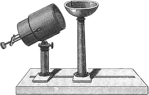 Acoustics; or the Theory of Sound
General Observations; Wave Motion
Before entering upon the theory of sound itself, it will be necessary to premise some observations upon the motion of waves in general, as these play a great part in this section of Physics.
Imagine a body making oscillations similar to those of a pendulum, in which, however, the relative positions of the different parts do not, as in the pendulum, remain the same; then these parts, to return to their original equilibrium, must likewise take up an oscillatory motion which differs from that of the pendulum, in that the mutual position of these particles changes every moment. Two conditions of things may here occur: either all the parts oscillate at the same instant and in the same time, or the oscillations may be propagated in different parts successively, so that one part may begin its motion when the preceding has ceased. The first case presents itself in a steel spring fastened at one end, or in a string attached at its two extremities; in the second case waves are produced, and an illustration furnished when a stone is dropped into still water. All these vibratory motions admit of various modifications in extent and rapidity; if they exceed a certain degree of velocity, their combined action produces wave movements in the surrounding medium, which are propagated to our organs of sense, and produce peculiar impressions upon them. These vibrations, within certain limits, produce waves in the air, consisting of alternate condensations and rarefactions, and are perceptible to our ears as tones; light, is the impression which a vastly more rapid vibration of particles produces upon our eyes, by inducing wave motions in a peculiar elastic fluid, the ether. It will therefore be necessary, as wave motion serves to propagate vibrations, to begin with that, and first to consider water waves, whose formation and conditions may be directly observed by us.
If a stone be dropped into water, it forms concentric circular waves, which consist of alternate elevations and depressions, in whose advancing motion the individual particles of water do not take part, as is shown by the fact that a floating body, although rising and falling, yet remains in the same place on the water. When regular waves are formed, the single particles of water on the surface, during the advance of the wave, describe curves returning into themselves, which are only closed when the succeeding wave is higher or lower: in cases of great regularity the curves are circles. Let us suppose that a motion, assumed to be perfectly regular, is propagated from one side to the other over a series of water particles, twelve for instance, then, when the first particle has completed its circular motion, the twelfth will be just beginning, and each intervening particle will be just one twelfth of its course behind the preceding. By means of these different motions is produced the curvilineal form of waves, and wave arcs are formed whose summits are where the water particle has completed its circuit, and begins a new one. The distance between two water particles in the same conditions of oscillation is called a wave length, and these particles have then precisely equal oscillations, while those lying on the half wave length are in precisely opposite conditions of oscillation. Other conditions occur where the motion is not perfectly regular, as then the paths cease to be circular, and frequently become elliptical, with the long diameter sometimes horizontal, sometimes vertical. If the horizontal diameter = 0, the particles oscillate only at right angles to the direction of the waves, and it is motion of this kind that propagates waves in a stretched cord. A cord wave, when reaching a certain point, is thrown back again, and may traverse the same route several times: two waves again may easily meet, and by their combination produce a standing wave.
Let us now examine the character of the motion of a cord or string during a standing vibration. A standing vibration of a string may be readily produced by taking one not too tightly stretched, and, drawing it out of the position of equilibrium, letting it go again. All parts will be simultaneously on one or the other side of the position of equilibrium,—they will be simultaneously at their maximum of distance from this position, the amplitude of oscillation only being different for each particle. The oscillations of a tense string when brought out of its equilibrium, or when disturbed by a bow drawn across its middle, are of precisely the same character; they are so rapid, however, as to be indistinguishable to the eye: they therefore give a tone. The standing vibrations in a string can also be shown by attaching one end, and with the other held in the hand, describing small circles, in which case the vibrations will form a great circle in the centre : accelerate the motion of the hand, and there will be in the middle of the string a point of rest, each half swinging as the whole did previously. Pl. 19, fig. 51, represents these vibrations: a is the point of rest; the nodes, ab and ac, are the vibrations or bellying of the string. Two nodes and three bellyings even may by a still greater velocity be produced. There is a better mode of observing these nodes than the one just mentioned: take a stretched string, bc (fig. 52), and place a rest at a, so that ab = \(\frac{1}{3}\)bc, and draw the bow of a fiddle across the smaller portion; the other portion will be set in vibration, and in such a manner that at the middle point there will be a second node, and consequently two bellies formed. The position of the node may be shown by its being the only point along the string where a small bit of paper laid across will not be thrown off by the vibrations of the string. Place the rest at one quarter of the length of the string, and there will be in the larger portion two nodes and three bellies.
It is not strings alone that vibrate in this manner: plates, bells, and smaller bodies may also be set in vibration, and exhibit certain vibration nodes To cause such bodies to vibrate, the apparatus, pl. 19, fig. 62, is employed, in which the plate of wood, glass, or metal, is laid upon the lower small cylinder, and then firmly fastened by means of the upper screw and a piece of cork. Set the plate into vibrations, which is best done by drawing across it a fiddle-bow, and the nodal lines and vibrating portions will be rendered evident by strewing over the plate fine sand or lycopodium. The powder is thrown up into the air when it falls upon the vibrating portions, and finally accumulates on the nodal lines, or lines of no vibration. They remain constant, therefore, and form the well known sound figures, first discovered by the eminent natural philosopher, Chladni. By taking sand moistened with gum water and finely pulverised, and placing a damp piece of paper on the plate, the figures may be removed and rendered permanent.
Different figures result with a variation of the point of support of the plate, the rapidity of the vibrations, and the point of application of the vibrating cause; of the hundreds fixed by Savart in the manner described above, we shall represent a few (figs. 63–74). The simple cross is produced when the plate is fastened in the middle and intonated at one corner; if the latter take place at the middle of one side of the plate, the cross (pl. 19, fig. 71) is formed, &c. Other of the four-sided figures represented, are obtained by preventing the vibrations of one or more points of an edge of the plate, in which case several nodal lines are formed; symmetrical figures, however, are always produced, as the vibration which is hindered on one side ceases also in the corresponding parts of the other three. Triangular and polygonal plates give similar results. In circular plates very different tones may be produced, and each tone has its proper figure. Here may be distinguished three kinds of figures: diametral, concentric, and mixed. The diametral figures are obtained in a manner similar to the method employed for figs. 63 or 71, and the nodal lines are then radii. In the concentric the nodal lines form concentric circles, and are obtained by piercing the centre of the plate, drawing the hair of the bow through the hole, and thus producing the intonation. The plate then needs only to be supported in some of the points through which the nodal lines are to pass. The figures of the mixed system consist of diametral and concentric more or less curved lines, as seen in figs. 75–83, and are obtained by fixing the plates in the centre, and pressing the figures upon the points through which the nodal lines are to pass. Stretched skins or membranes act in the same manner as the plates, and Marx has exhibited the sound figures of these by means of his instrument, the Eoline.
Normal vibrations occur in bells as in plates; and here also nodal lines are formed, which are, however, sometimes exceedingly irregular. To render these vibrations visible, we make use of a large wine-glass with a foot (fig. 84), filled with water or mercury, and intonated on the edge. There are then formed two very evident diametral nodal lines, between which the fluid remains in constant vibration, sufficiently violent at times to throw up drops into the air.
In vacuo nodal lines are obtained which do not always agree with those formed in the air, particularly when the powder employed is very light, as lycopodium.
Plates, bells, &c., which do not possess equal elasticity on all sides, likewise form peculiar figures, which, however, cease to be strictly symmetrical.
Transmission of Sound through the Air
By the vibration of a body a wave motion is communicated to the surrounding air, and this it is which brings the tone, arising in the vibration, to our ears. Not air alone, however, but every elastic medium, can propagate sound; in a vacuum this propagation does not take place. Of this fact we may be convinced by placing a small bell, moved by spring clockwork, and isolated by being set on a woollen mat, in the receiver of an air-pump. Cause the hammer of the bell to commence striking, and with an increasing rarefaction of the air, the sound will become fainter and fainter, until it disappears almost entirely. Re-admit the air, and the sound will be again audible, becoming more and more distinct. Saussure found, that on the summit of Mont Blanc, a pistol-shot made only an inconsiderable sound: and Gay Lussac noticed, that when at a height of about 3000 feet in a balloon, his voice became less powerful. The loudest sound does not pass beyond the atmosphere, and terrible explosions might take place on the moon without our hearing anything of them. Water transmits sound very well, since divers hear at the bottom of the water, the voices of persons speaking on the shore.
The manner in which the vibrations of sound are propagated through the air, may be best understood by supposing an open tube, bdtt′ (fig. 49a, pl. 19), in which, from t′b, a piston may be moved quickly backwards and forwards. Suppose the length of the tube to be divided into a number of parts, equal to the length of the play of the piston, about in s, a, b, c; then when the piston is forced into a′, the air between a′p will fall into a vibratory motion, and this motion will be transmitted to the layer ps, when the piston has reached p, and will pass over into the second half to b, when the piston has finished its advance and commenced its return. This motion cannot, however, be uniform, for previously mentioned reasons, and we obtain the velocity in the individual parts by describing a semicircle above sa, the length of the play of the piston, dividing this semicircle, as at x′ and y′, into equal parts, and letting fall the perpendiculars, xx′ and yy′. The motion must, from the elasticity of the air, be transmitted successively to all the strata, while, if the air were inelastic, the piston would drive out all the air before it. From these considerations we may readily understand, that during the ingress of the piston, the air in bs becomes compressed before the motion is transmitted to sa. When the piston begins its return, the compression is propagated to sa; the strata between s and b, however, enter upon a retrograde motion, and when the piston has reached b again, occupy their old position. With a new action of the piston, the first vibration passes over to ab; while the layers between a and s are making their retrograde motion, those, however, between s and b are compressed, &c. Sound waves are consequently formed, each of which has the duration of a forward and backward motion of the piston, and consists of a rarefied and a condensed part, which then corresponds to the wave valley and wave elevation.
The velocity with which the waves are propagated through the air is independent of the velocity of the action of the piston and of the individual strata of air; as, however, experiment has shown that the velocity of propagation of air waves is independent of the time in which each individual part completes its oscillation, and the wave length is the distance by which the wave advances while a single layer makes a complete vibration, the wave lengths must increase in the same proportion as the time of vibrations of the individual particles of air. Thus, if the piston require triple or quadruple the time to make a complete backward and forward motion, the wave lengths will be three or four times as great.
We have thus considered the transmission of air waves in tubes: in the open air they must be transmitted in precisely the same manner in all directions.
The impression produced upon the ear in this motion of air waves is very different according to their character. If the motion be produced by a single blow, and this not repeated, as in a pistol shot, where thus the air is suddenly and powerfully condensed, and then advancing as before mentioned, we hear a report; in regularly successive vibrations we hear a tone; and if the successive vibrations become more and more irregular, we have a noise. The tone itself will be higher as the length of oscillation or the wave length is shorter: it becomes stronger or more intense as the amplitude of oscillations in the sounding body is greater, for so much the greater is the degree of condensation and consequent rarefaction of the air waves.
The velocity with which tones are transmitted through the air is constantly the same, whether they be high or low, strong or feeble. Experiments were instituted in 1822 by the Bureau des Longitudes, accurately to determine this velocity, whence it resulted that sound travelled 310.88 metres, or about 1050 Paris feet in a second. During these experiments the thermometer stood at 60°F., the barometer at 756.5 millimetres, and the hygrometer at 78°. Experiments recently performed by Sir John Herschel give 1125 English feet per second as the rate of transmission at 62\(\frac{1}{2}\)°F. Above 62\(\frac{1}{2}\)°F., each degree adds 1.14 feet to this velocity, and below this temperature the velocity is diminished in the same ratio.
As light travels faster than sound, it will be readily understood why the flash of a gun may be seen before hearing the report, and the lightning be observed long before the thunder reaches us, the interval depending upon the distance at which the phenomenon takes place. But for the numerous corrections required by the varying temperature, density, and hygrometric condition of the air, it would be an easy matter to determine the distance by this interval.
Reflection of Sound
Whenever a sound attempts to pass from one medium into another, as from air into water, or from one gas 10 another, it experiences a partial reflection; this, however, is strongest when the sound strikes against a solid body; and when the body possesses very little elasticity, the reflection may be total. In this latter case, the law that the angle of reflection is equal to the angle of incidence prevails; in the former, while one part is reflected according to the same law, the remainder is transmitted.
Upon this law of reflection depends the phenomenon called the echo. When sound strikes the reflecting surface at a right angle, it is thrown back again, and the quickness of the return depends on the distance from this surface. If this amount to 1125 feet, then the sound will complete its advance and return in two seconds : the tone will then be again heard after this time. As many syllables will be reflected by the echo as can be spoken in this time: the number may amount to seven or eight. The number of syllables repeated by an echo does not depend, then, so much upon rapidity of utterance, as upon the distance of the reflecting surface. At sea it has been found that even clouds have served as reflecting surfaces, so that it would seem as if the surface struck need not necessarily be a solid body.
An echo often repeats the same syllable several times, this being produced by successive reflections of the same tone from different surfaces, or from two surfaces parallel to each other. Thus, from the top of the Rosstrappe in the Harz, the discharge of a pistol gives a manifold echo resembling rolling thunder.
Here belongs the echo which returns a tone to a given spot, so as to be inaudible at a very short distance from it. Suppose an elliptical dome (pl. 19, fig. 93), aba′, whose foci are f and f′. A word spoken at one focus will be reflected to the other, and will be inaudible in the space between f and f′; a light whisper will be understood even if the distance between these points amounts to 80 or more feet. This phenomenon depends upon the fact that if lines be drawn from f and f′ to i and i′, and any other points of the curve, these lines drawn to any one point will always make the same angle with the perpendicular at this point. Another phenomenon, such as occurs in the Rathskeller in Bremen, where the ticking of a clock in one corner of the arch is heard in the other, depends upon the fact that the flutings used to ornament the arches supply the place of tubes, which propagate sound better than the open air.
The construction of rooms for public speaking or music, involves to a great extent the principles of the reflection of sound; into all such constructions the parabola enters, or should enter, very largely, as a sound produced in the focus of a parabola is reflected in every direction with the greatest possible uniformity.
Formation of Musical Tones
If we have a tube closed at one end, at the open end of which a sound wave enters, this latter will be transmitted to the other extremity and there be reflected. Standing vibrations may then be formed in the tube itself by the opposite action of the reflected and re-entering wave, as all the single strata in the tube begin their motion at the same time, attain at the same time the maximum of their velocity, and likewise reach simultaneously the terminus of their path, again to recommence in an inverted order. In standing wave vibrations of this character, the air is condensed uniformly in the tube when the single strata of air pass their position of equilibrium with the maximum of their velocity: if the particles have arrived at the extreme points of their course in their oscillation towards the closed end of the tube, the greatest condensation here takes place. If, now, they begin to return after half an undulation, a rarefaction takes place at the closed end of the tube; at the open end there is neither a marked condensation nor rarefaction. When the tube has an opening in any part of its length, the formation of a standing wave experiences an interruption, since in the moment of greatest condensation the air can escape, and can enter during the rarefaction; this circumstance operates less as the aperture is nearer the open end, since here neither the condensation nor the rarefaction is so great as to exercise any material influence. Cutting off the tube at this place would produce the same effect, and the sound waves would thus be no longer than from the beginning of the tube to the orifice.
The formation of a standing air wave depends, then, upon the relation between the length of the tube and the wave length of the incident tone; it is also essential to the formation of a. standing wave in the tube, that close to the bottom the amplitude of oscillation shall become almost nothing; that there the alternating condensations and rarefactions shall take place, while at the open end they must not occur. To this end the distance of the opening from the bottom of the tube must be \(\frac{1}{4}\), \(\frac{3}{4}\), \(\frac{5}{4}\), \(\frac{7}{4}\), &c., of a wave length, and we then obtain in the tube vibration nodes similar to those which we have already found to exist in strings and plates.
To put the air in a closed tube into such vibration, we need only bring an oscillating body near the open end of the tube, which shall give such a tone that the length of the tube has one of the above proportions (\(\frac{1}{4}\), \(\frac{3}{4}\), &c.) to the wave length. If, for example, a vibrating tuning fork be placed about two inches above the open extremity of a glass tube closed below, then if the latter is of the proper length, the two will become resonant, in which case the strata of air contained in the tube will be put into a condition of standing vibrations. By this means the tone of the tuning fork is increased considerably in intensity. If the tube be too long for the sounding body, it may be shortened to the proper length by pouring in water. Instead of the tuning fork, one of the glass plates used in the production of sound figures, or a glass bell, may be intonated with a fiddle-bow before the opening. Savart constructed for this purpose the apparatus represented in pl. 19, fig. 92. It consists of two wide tubes, movable one within the other by means of a screw, by which the sound tube may be lengthened or shortened at pleasure. Before the opening of the tube stands a glass bell which can be sounded by means of a fiddle-bow. Bringing the tube to the proper length, the sound of the bell will be much increased in intensity; removing the bell from the vicinity of the tube, by sliding it along the groove in the base of the apparatus, the tone will become remarkably thinner.
The air within a tube may also be put into standing vibrations by causing a current of air, flowing past the tube, to break against the edges of the opening, waves being thus produced which are reflected from the bottom, and interfere with those subsequently created. In narrow tubes the air may be set into standing vibrations by bringing the open end of the tube against the lower lip, and blowing into it obliquely against the edge. The tones will be deeper in proportion to the length of the tube, and inversely. The so-called Pan’s pipe is an illustration of this condition of things.
Upon the principles just explained depends the construction of organ pipes, which are made principally of wood, in which case they are four-cornered, or of tin, when they are made cylindrical. Figs. 53 and 54 represent the form of the wooden, and figs. 55, 56, and 57, that of tin pipes. Such a pipe consists of the foot or pedal, p, the labium or mouth-piece, b, b′, and the tube. The pedal is hollow and sharpened to a cone below, to place it in the sound-board from which the pipe receives the air, which is to produce in it the vibrations of sound waves; above the widest part of the pedal is placed a bridge, l, which contracts the opening to a very fine slit, and thus directs the entering column of air against the sharp edge of the labium. The pipes themselves are supplied with air by means of a pair of bellows, a very convenient apparatus for which is exhibited in pl. 19, fig. 58. Between the feet of a small table, ss′, is attached a bellows, set in operation by the foot-board, p, and forcing its wind into the superincumbent wind box, which sends it through the tube, ff, into the upper sounding-board, cc. As this wind box, by continued motion of the bellows, will soon become full, if little air is used, a lever connected with a valve in the wind box strikes against a pin attached to ff, and thus lets out the superfluous air. The rod, tt′, serves to give greater pressure to the wind box where a sharper current is required. In the upper floor of the sound-board are several holes, oo′, generally twelve, in which pipes may be inserted. These holes are always closed with valves, which may be opened by a register at hh′, upon which the air can enter into the pipes and cause them to sound. With a feebler wind the same pipes give a lower, and with a stronger a higher tone.
Not covered tubes alone, or those closed at the upper end, can be thus intonated, but also those open above, and in precisely the same manner. In these the short and narrow tubes will always give the higher tone. Another method of employing open tubes consists in generating hydrogen gas in the apparatus represented in fig. 91, letting it escape through a fine mouthpiece, and after setting it on fire, placing a tube, ab, over the jet.
Standing vibrations arise in an open tube, from the circumstance that a greater condensation takes place in the middle, the particles of air not being able to escape; as soon as this condensed portion comes to the open end of the tube, the particles expand, thus producing a rarefaction, which, sent back, traverses the tube in the opposite direction. As, however, at the open end a condensation and a rarefaction coincide, no vibration nodes can here occur, these necessarily existing in the inner portions of the tube; if, therefore, the deepest tone of an open tube is to be equal to that of a closed, the former must be twice the length of the latter.
If holes capable of being closed by a slide, are made in different parts of an organ pipe, it may be shown that the tone remains unchanged if the opening exists at a belly, while another tone is produced if the opening is made at a vibration node.
However little the influence exerted upon the tone of a pipe by the direction in which the current of air strikes the mouth-opening, so much the more considerable is the effect produced by the shape of the labium, and the height of the air-hole.
The walls including a vibratory mass of air exert a great influence upon the tone, and a pipe constructed of poor tin, or of soft or resinous wood, gives constantly a smothered feeble tone; even moisture upon the wood pioduces the effect of lowering the tone.
With regard to the musical notes produced by organ pipes, let us call that tone produced by a pipe four feet long, the fundamental note C. If we examine the pipes whose tones harmonize with that of C, we shall find that the rapidity of oscillation of notes produced by them, stands in a simple relation with that of C; the pipes will therefore be \(\frac{1}{2}\), \(\frac{2}{3}\), \(\frac{3}{4}\), \(\frac{5}{6}\), &c., the length of C. A pipe of half the length gives then the octave; that whose length is two thirds, and which makes three oscillations to two of C, is the fifth; three fourths the length gives the fourth; four fifths of the length gives the major third; and five sixths the minor third. The intermediate tones are obtained by taking one of the pipes in question as the fundamental tone and finding its accord. Thus we obtain for the G accord the fifth D, if we take a pipe two thirds the length of G, and the major third H with a pipe of four fifths, and the minor third B with one of five sixths the length of G, &c.
The deepest tone in music is that C given by a covered pipe of sixteen feet in length, or an open one of thirty- two feet. We know, however, that for the deepest note of a covered pipe, its wave length must be exactly one fourth of the wave length of the tone; in the open air, therefore, the wave length of this amounts to 64 feet. Sound travels about 1050 German feet in a second, hence it follows that to produce this deepest note there must be \({\Large \frac{1050}{64}}\) or 16.4 oscillations in a second (more correctly, perhaps, \({\Large \frac{1125}{64}}\) or 17.5). We obtain the number of vibrations necessary to bring out the deepest tone of any covered pipe, by dividing 1050 by four times its length. Thus the C’s forming the six lower octaves make respectively 16.5, 33, 66, 132, 264, and 528 vibrations in a second. The greatest number of vibrations observed in a second amounts to 24,000; the tone thus produced is, however, scarcely audible: the deepest audible tone is that produced by 7.8 vibrations. Still higher and deeper tones may perhaps be produced and rendered audible by artificial means.
The length of pipes gives a ready method of determining the number of vibrations: this is nevertheless not entirely exact, and Cagniard de la Tour has invented a special apparatus by means of which the absolute number of vibrations in a tone can be accurately determined. This instrument is represented in pl. 19, figs. 59–61, where t, t′, f, f, is a round box of brass about two or three inches broad and one inch high, whose upper surface is perfectly plane and well polished; there is an opening in the middle of the bottom ff′, into which the air tube, gg′, is screwed. In the bottom, tt′, represented from above, and laterally in fig. 60. a number of holes equidistant from each other are bored, their interspaces being somewhat greater than the diameter of the holes, which generally amount to ten; pp′ is a movable plate, ground upon the plate tt′, and provided with holes corresponding in size, number, and position, with tt′, so that by turning pp′ about its axis, x, on tt′, all the holes may be simultaneously opened or closed. At the upper extremity of the axis x there is an endless screw, catching in a wheel, rr′, of 100 teeth; ec′ is a second wheel of 100 teeth, standing in such connexion with the first that it completes only one revolution while the first makes 100, an arm on the axis of the first wheel pushing the second forwards by one tooth at each revolution. The axes of these two wheels carry indices, which mark on the dials attached to the side plate (as represented in fig. 61) the revolutions and their fractions. To start this part of the machinery, or arrest its motion at any moment, the axis of the wheel rr′ is united in such a manner with the buttons b and b′, that this wheel can either be caught in the endless screw or separated from it. The apertures in the plates tt′ and pp′ are directed obliquely to the surface, so that the air rushing through gg′ is capable of causing a rapid rotation of the plate pp′. Suppose, now, that in the movable disk there are ten holes, and in the other only one, then this would be opened and shut ten times in a revolution of the plate: there thus arise ten complete sound waves in one revolution, of which there may be 1, 10, 100, &c., in a second, so that all the tones may thus be produced. The lower plate has, however, ten holes; and as each one exerts its influence, there is produced a strong lasting tone.
To count vibrations with this instrument (called by its inventor the Siren), place upon the sound-board (fig. 58) a concordant pipe, as the a of the common tuning fork, and near it the siren in another hole of the sound board. Allow the air to enter, and regulate the pressure upon the wind box by the rod t, until the two are in unison; then couple the wheel of the siren, and allow it to revolve a certain time by a seconds-watch. Stop the motion of both watch and siren, and from the latter may be obtained the entire number of revolutions, and from the former the number of seconds; comparing the two will give us the number per second. We shall then find that in one second 440 revolutions have been made, which is really the number of vibrations for the tone a of the tuning fork.
The vibrations of strings are much too rapid to admit of their being counted; they are even visible only in the longest and deepest strings. It was known very early that the tone of a string was higher the more the string was stretched, or when it was shortened. It was not possible, however, to indicate by means of calculation the connexion between the tone of a string, its tension, its length, and the rapidity of its vibration. The eminent philosophers, Taylor, the two Bernouillis, d’Alembert, and Euler, occupied themselves with the investigations of this relation; Lagrange, however, was the first fully to elucidate it. The propositions established by him are the following: 1. The number of vibrations of a string is inversely as the length, that is, half the string makes twice the vibrations of the whole, &c. 2. The number of vibrations is proportional to the square root of the stretching weights, that is, four times the weight produces twice the number of vibrations. 3, The number of vibrations of cords of the same material is inversely as their thickness, that is, a string half as thick as another makes twice the number of vibrations in the same time. 4. The number of vibrations of strings of different material is inversely as the square roots of their densities: thus, taking a string of copper whose density is 9, and a string of catgut whose density is 1, their diameters and lengths being equal, the latter will make three vibrations in the same time that the first makes one.
The Monochord, invented by Savart, and represented in pl. 19, fig. 50, is used for determining the laws of oscillation of stretched strings, and their tones. It consists principally of a hollow box, ss′. At c is a bridge with slits in which the strings are fixed, which then pass over the two bridges, f and m, and beyond m may be stretched by weights. A third bridge, h, may be moved along under the strings without touching them, and any point of the string may be pressed down upon it by means of a binding screw. By moving along this bridge, all the notes of an octave may be produced, and we shall find that the lengths for a fundamental note c = 1 are in the following proportion: c = 1, d = \(\frac{8}{9}\), e = \(\frac{4}{5}\), f = \(\frac{3}{4}\), g = \(\frac{2}{3}\), a = \(\frac{3}{5}\), b = \(\frac{8}{15}\), c = \(\frac{1}{2}\), the same ratio that is found to exist in organ pipes. These ratios confirm, at the same time, Nos. 1 and 2 of the propositions just adduced; for to obtain, for instance, the octave of the fundamental note by tension, it is necessary to attach four times, and for the fifth, nine times the weight, &c.
Of Longitudinal Vibrations
Strings and rods have not only transverse vibrations, such as we have already considered, but they also vibrate longitudinally, like the air inclosed in a tube. This is shown by rubbing a glass tube longitudinally with a damp finger, or drawing a fiddle-bow across it at a very acute angle. The same takes place in massive rods of glass, metal, or wood, although here it becomes necessary to make use of a piece of rag, sprinkled with powdered rosin. It is, however, more convenient to make use of a so-called sounding rod, namely, a short glass tube whose axis is made a continuation of that of the body to be set into vibration. Vibrations produced in the first by rubbing with a damp cloth, will then be communicated to the second, and the two will vibrate together. Straight rods held in the middle and free at the extremities vibrate like open tubes; and all rods of equal length, whatever be their thickness, give the same tones. Nodal lines are also formed on the rods, consisting of the points of rest formed by the individual molecules during their motion produced by the vibrations. These nodal lines form peculiar curves, which exhibit a certain similarity to a greatly elongated helix, forming a node at each revolution. The inner surface of a vibrating tube presents nodal lines similar to those of a rod. In prismatic rods the nodal lines are more complicated.
Tongue Work and Reed Pipes
Any thin plate set into vibration by a current is called a tongue. Thus, in pl. 19, fig. 95, ll is a tongue, which, by means of a small screw, is so attached to a plate that it can vibrate in the little aperture, nbcd, without touching the edges. The plate may be of brass or zinc; the tongue, ll, should be a very thin elastic slip of brass. The current must be directed against the free end of the tongue, ll; sounding vibrations are thus produced by the alternate opening and closing of the aperture, whose length depends upon the number of vibrations of the tongue. The accordeon is a combination of several tongues, yielding the successive notes of the scale; these are placed upon a sound-board, and played upon by air from a bellows. Each tongue has its valve, which may be opened by a stop, and the air thus admitted to produce vibrations in the tongue.
The tongue-work in an organ has a similar construction, although the attachment is somewhat different. Fig. 97 represents the arrangement on a large scale. The tongue-work consists of a pedal, p, in which is a hollow channel, which appears above as a round hole. This channel is closed by the plate r, in whose opening is the tongue l, to be vibrated by the air passing through the channel. To tune the tongue its length must be changed, for which purpose there is a tuning-wire passing through the pedal, and by its two extremities pressing the tongue against the plate. The vibration of that part of the tongue between the plate and the wire is thus prevented.
This tongue-work is combined with the pipe, t (fig. 96), in such a manner, that the air entering through the pedal of the pipe presses against the tongue, setting it in vibration. It then escapes through an opening in the head, t′. When the pipe is used, by way of illustration, a glass plate lies before ab, to exhibit the action of the tongue. Sometimes, and generally in organs, the tongue-work is placed in the pedal, and the tube is then directed upwards.
The form of the tube gives character to the tone; thus the trumpet works have tin tubes widening above, &c. In such tongue-work, however, the vibrations of the tongue depend upon the motion of the column vibrating in the long tube, and the tongue is more vibrated than if it made entirely independent vibrations.
On the Beats of Tones
If two tuning-forks of very nearly the same pitch, or two strings or pipes of almost precisely the same tone, be sounded simultaneously, we shall hear a variation of the tone, consisting in an alternate increase or diminution of its intensity. This is caused by the fact, that both sounds are produced by undulations of very nearly, but not quite the same rapidity, so that at one time these will come together in the same phase of vibration, and at another time in opposite phases. In the first case the intensity will be double that of a single sound; in the latter, no sound whatever would be perceived but for the momentary persistence in the ear of the sound of the instant previous. The tone will consist then in a gradual increase or diminution between these extremes. The greater the difference in the rapidity of undulation, the more frequent will be these beats; when the two instruments are in unison they cease entirely. Any number of strings may thus be brought into unison by tuning until the beats are found to have disappeared altogether. When two sounds are heard, of which the vibrations stand in a simple ratio to each other, as of two to three, three to four, or four to five, and in which the coincidence of two impulses or undulations recurs with sufficient frequency, a third sound is produced by this coincidence, always deeper than the primary notes, and generally the fifth or the octave below the lower of the two. These are called tones of combination, or the accessory sounds of Tartini, and must not be confounded with harmonic notes.
Sound in various Media
Sound diffuses itself through all ponderable matter, although with various velocities. Newton gave an expression for the motion of sound in the air, which was much too small, being but about five sixths of the actually observed velocity; Laplace explained the difference by showing that a motion of sound cannot take place but by compression of the molecules of the air, during which, in all cases, there must be a development of heat; and that then the heat, now become sensible, must influence the law of elasticity in such a manner as to bring about an acceleration in the transmission of sound. Consequently, temperature would influence the motion of sound, as we find to be actually the case. Laplace has given a formula for the rapidity of this motion in vapors and gases; according to him, \(v=\sqrt{gmb(1+at)k}\), where v is the velocity in a second; g, the accelerating force of gravity, 386.29 inches; m, the ratio of the density of mercury to that of atmospheric air, found by experiment to be 10.466, at a temperature of 32° F., and a barometric pressure of 29.927; b, the standard height of mercury in the barometer; a, the constant co-efficient of expansion, ascertained by experiment to be .00208; and k, the square-root of the quotient, which is found by dividing the number which expresses the specific heat of the air (or other gas) under a constant pressure, by that which expresses its specific heat under a constant volume. The value of k for atmospheric air has been found to be 1.421, hence \(\sqrt{k}\) = 1.192, and substituting the various values in the above formula, it becomes v = 916 × 1.192 (1 + .00104t) = 1092 + 1.14t, where t is the number of degrees above 32° F. The velocity of sound in the air is therefore dependent upon the temperature, and not upon the pressure of the atmosphere. From this formula the velocity of sound in other gases may be determined, whenever the value of k is known, or k may be determined from the known velocity.
Since sound depends upon condensations and rarefactions, and such media alone can propagate it as are capable of this, it follows that this velocity of sound in fluids depends upon their compressibility. This compressibility must be obtained by direct measurement, for which purpose Oersted invented the Piezometer. By the use of this instrument and calculation, it has been found that in water of 54° F., the velocity of sound in a second amounts to 4630 feet; direct experiments by Colladon, in the Lake of Geneva, have given results indicating a velocity inferior to the above by less than sixty feet.
The same principle holds good in general for solid bodies. Chladni and Savart have instituted very extended experiments on this subject, and have found that this velocity is universally greater than in the air, being least, however, in whalebone, where it amounts to 6\(\frac{2}{3}\) times, and greatest in deal, where it is 18 times greater than that in the air.
If several solid bodies be united together, sound is transmitted with great facility throughout the whole mass, and, arrived at the extremity, the sound waves partly pass into the contiguous medium, whether fluid or gaseous; they are, however, partly reflected, and form their standing vibrations with the re-entering waves. If. however, the whole system of bodies is set into vibration simultaneously with each individual point, they lose their individual character in a great measure by this union. Upon this circumstance, among others, depends the variety of musical instruments, and this is the reason why, for example, two equally proportioned pianos may exhibit a very different character with respect to sound and tone.
Although vibrations are readily transmitted over a system of uniform bodies, solids for instance, this takes place with more difficulty when the bodies are different, as from solids to fluids or gases. Here the vibrations of the sounding body must be communicated to another, for the purpose of being increased in intensity : in other words, its vibrations are strengthened by resonance. An example has already been given of the strengthening of sound by a tube; another is to be found in the sounding board, where the vibrating strings are brought into contact with a large thin surface easily set into vibration.
In a similar manner bodies may be set into vibration by a sound wave in the air, as a door, a window, and even strings themselves. Here the sound waves in the air, started by the vibrations of a solid body, or even the original vibration of the air itself, come in contact with the body, causing it to vibrate in concert. Savart has ocularly demonstrated such sympathetic vibrations in the shape of sound figures, a few of which are represented in pl. 19, figs. 85–90. These were produced by stretching a membrane over a wooden hoop or glass bell, sprinkling it with fine sand, and causing in it a sympathetic vibration, by means of an approximated tuning-fork or organ pipe. The whole series of figures here answers to one and the same tone, their different forms being produced by making the tone higher or lower.
Voice and Hearing
For a description of the organs of voice and hearing existing in the animal body, we must refer our readers to the section Anthropology, and confine ourselves here to the consideration of the more strictly physical part of the subject, how a tone is produced and modified by the larynx. The larynx consists of four cartilages: the cricoid, the thyroid, and the two arytenoid, which are intimately connected with the windpipe and form its continuation, contracting to a mere slit, the glottis. This may be opened or closed by means of muscles attached to the cartilages forming its walls. Over this glottis lie two sack-like cavities, the ventriculi morgagnii, whose upper edges form a second glottis half an inch above the first. The whole is covered by the epiglottis, which prevents solid particles of food from entering the trachea, while passing through the oesophagus to the stomach. Various individuals, as Biot, Ferrain, and Cagniard de la Tour, have instituted experiments with caoutchouc on the formation of tones by the organs of voice; the most satisfactory, however, are those of Müller, performed with separated larynges. Pl. 19, fig. 98, represents such a larynx attached to a board, f, the larynx terminating with the chordæ vocales, which are stretched between a and b. a is one of the arytenoid cartilages (the other is behind it), b is the under side of the thyroid cartilage, d the inner membrane of the larynx which ends in the chordæ vocales, which are stretched between a and h. The upper parts are not represented, for the sake of greater clearness of the figure. If such a larynx be blown through by means of the air-tube, u, it gives a tone precisely similar to that of the human voice, which is strength ened, not altered, by the upper parts, which vibrate and intonate at the same time. The change of tone is produced merely by the greater or less tension of the chordæ vocales, this being effected by the action of special muscles in approximating or separating the cartilages. This motion is imitated by the strings x and y, which are loaded with weights. In this manner Müller was enabled to produce all the tones of the human organ, the higher by drawing x, the lower by means of y. In animals, the organs of voice are constructed on the same plan, but with different modifications.
The organ of hearing consists of three parts : the external ear, the cavity of the tympanum, and the labyrinth. The external ear serves by means of the concha to catch external vibrations and to convey them through the meatus externus to the tympanum, which separates the outer from the inner chamber. This tympanum is a membrane stretched over a long hoop, and to its inner surface is attached a small bone, forming one of a connected series of four—the malleus, the incus, the os orbiculare, and the stapes. The aerial undulations are transmitted from the tympanum, by means of this series of bones, to two openings, the fenestra ovalis and the fenestra rotunda, in the labyrinth. This consists of several long excavations filled with a fluid in which the auditory nerve is expanded, passing in very fine ramifications into the cochlea. These various parts will be found represented in the anatomical portion of the work, to which we refer our readers.
The precise function of the individual parts of the ear is not so well established as in the case of the larynx. The tympanum, however, serves essentially in hearing by its greater or less tension, and upon its sound condition depends, to a considerable extent, the excellence of hearing. The application of the hearing tube (pl. 19, fig. 94) gives a proof of this, for in its employment the hearing is better when the sound waves received in the funnel, cc′, are concentrated in the tube tt′, and by means of the aperture mm′ are conducted towards the tympanum. By this means the latter is set into more vigorous vibrations, and the tone strengthened without the internal portion of the ear being directly affected.
![]() Pyronomics; or the Science of Heat
Pyronomics; or the Science of Heat
 Pyronomics; or the Science of Heat
Expansion of Bodies of Heat
Our knowledge of heat is limited almost entirely to its effects; of its true, nature we know almost nothing. It cannot lie concealed in the interior of bodies, as in this case the refinements of modern chemical analysis would obtain some indications of its presence.
The term heat, then, is to be understood as expressing an effect; when it has reference to a cause, it will be readily intelligible from the context.
One of the most remarkable properties of heat is, that it expands all bodies; this expansion, as a general rule, increasing with the increment of heat. It is greatest in elastic fluids or gases, and least in solids.
As all bodies are expanded by heat, the amount of expansion of a body may serve to measure the degree of its heat. For a moderate range of temperature, the expansion of liquids is employed; for very elevated points, however, the extension of a solid must be substituted. Heat measures of the first kind are called Thermometers; of the second, Pyrometers.
If a glass tube with a bulb at one end be partly filled with a liquid, and if the upper part of the tube be melted together, after a vacuum has been formed in the portion not occupied by the liquid, then, by heating the ball the liquid will expand, and will rise in the tube without obstruction, owing to the vacuum above. If now the tube be graduated to a certain number of equal parts, the proportional elevation of temperature can, in every case, be determined. For filling the tube either colored alcohol or mercury may be employed. The latter is most generally advisable, on account of its retaining its fluidity at a low degree of temperature, not vaporizing but with a considerable degree of heat. In addition to this, its expansion, without the ordinary range of temperature, is in direct proportion to the increment of heat.
The Mercurial Thermometer (pl. 19, fig. 7) consists of a narrow cylindrical glass tube, with a bulb blown at one end, the whole, except part of the tube, filled with mercury. The space above the mercury is a vacuum; the upper end of the tube is hermetically sealed. The filling of the thermometer is effected by atmospheric pressure. Thus, the empty tube is heated as much as possible, and the open end immersed in a vessel of mercury. A partial vacuum being formed on the cooling of the tube by contact with the mercury, a certain portion of this liquid is driven into it. If a sufficient amount be not yet introduced, the mercury already in the tube is made to boil, and, after the empty space is filled with the vapor, the tube is again inserted in the vessel of mercury as before. When the tube becomes thus completely filled with mercury at an elevated temperature, its upper end is hermetically sealed by being brought into the flame of a blow-pipe. On the contraction of the mercury by cooling, the empty space left is a perfect vacuum. The height of the mercury in the tube is measured by the scale or graduated division attached to it. This scale is constructed by fixing in the first place two points of temperature corresponding to the freezing and the boiling points of water. To obtain the former, immerse the thermometer in a quantity of finely pounded ice melting into water, and after a short time mark the elevation of the mercury upon the tube by making there a fine mark or scratch. For the latter, take a long-necked vessel filled with distilled water, and after causing the water to boil, again immerse the thermometer tube. The elevation of the mercury, after a short time, must be again marked on the tube, as being indicative of the boiling point of water. The distance between these two points, the freezing and the boiling points of water, being thus obtained, the intervening space may be divided into any number of parts. In the scale of Reaumur it is divided into eighty, and in that of Celsius or the centigrade thermometer, into 100 parts, the zero being at the melting point of ice. Graduations of the centigrade thermometer over 360° above zero, and 30° or 40° below zero, are hardly available, as these degrees are too close to the boiling and freezing points of mercury, near which the expansion and contraction are not in precise proportion to the variation of temperature.
Besides these two scales, the first of which (Reaumur’s) is chiefly used in Germany, the second (the centigrade) in France, there is still a third (the Fahrenheit) employed in England and America. Fahrenheit, seeking to avoid negative quantities, obtained, as he thought, the point of maximum cold, by mixing salt and ice together; this he called zero of his scale. He divided the interval between this and the boiling point into 212 equal parts, the freezing point falling at 32°, and thus gained the advantage of having fewer fractional quantities in estimations of temperature by his instrument. There are, of course, 180 degrees between the freezing and boiling points, so that 0° of Reaumur or Celsius (R. or C.) = 32 F. It is customary in graduating for the Fahrenheit scale, to call the melting point of ice 32°, and marking off about 70° below this point equal to 70° above it.
The measurement of temperature by means of the thermometer is exceedingly simple, all that is necessary being to bring the bulb in communication with the temperature to be measured, and marking the elevation of the mercury after it has become stationary.
As before observed, solids expand much less than liquids and gases, and must therefore be employed when high degrees of temperature are to be determined. As this expansion is of very small amount, it becomes necessary to resort to some contrivance for rendering it sensible. Now, if a rod be placed in contact with the short arm of a lever, the other being much longer, and its point serving as an index to a circularly graduated scale, then a slight expansion of the rod acting on the short arm will cause a considerable traverse of the other over its graduated scale. A better arrangement for this purpose is the apparatus of Lavoisier and Laplace, represented in pl. 19, fig. 8. A rod, a, of the material to be tested lies horizontally upon glass bars, one end resting against a vertical glass bar, b, which is suspended to a horizontal iron cross-bar, whose extremities are cemented into two massive stone pillars. The other end of the rod a is in immediate contact with a similar glass bar, c, carried by a bar, d, movable about its axis. To the prolongation of this latter bar, d, a telescope is attached, directed towards a distant scale. If, by the expansion of the rod a, the lower end of c be ever so slightly moved, the telescope will be turned, and its sight line, directed to another part of the scale, will indicate the amount of rotation. A box filled with heated water or oil is placed between the four pillars, for the purpose of heating the body to be examined, when dipped into it. This apparatus answers only for indicating temperatures below the boiling point of oil, as about 300° R = 707° F.
For higher temperatures, the apparatus represented in figs. 9–11 is better adapted: f is a strong iron plate, upon which is fastened an alidade, ab, turning about the point a. This carries a telescope, g, while a second telescope is fastened to the iron plate itself at c and d. A rod, mn, is now brought in front of the two telescopes, so that its extremities fall in the centre of the field as indicated by the cross hairs. If the rod be increased in length to m′n, the extremity n remaining fixed, the alidade must be turned until the extremity m′ again falls in the centre of the field of the telescope g. The amount of this rotation is measured on a circular scale attached to the plate f. If the proportion between am and ab be known, then, from the arc VV′ is obtained the desired extension, mm′, for \({\Large \frac{mm'}{\mathrm{VV'}}}={\Large \frac{am}{\mathrm{ab}}}\). The adjusting screw, r, serves to shift the alidade by a very slight amount, for the purpose of adjusting the telescope g. For temperatures below 300°R., a copper box is used, placed upon a furnace and filled with oil. The bar to be examined is placed upon an iron support, which rests on the box. The extremities of the bar mn lie opposite to two lateral apertures, closed by glass plates. For higher temperatures, the bar is placed on a support, likewise iron, in a brick furnace, in which are small holes opposite to the telescopes.
As it is in our power, from the known temperature, to determine the extension of any body, so, conversely, from the known extension of a body, the temperature to which it is exposed may be ascertained. The ordinary thermometers range only to about 360°C, or 660°F., above which mercury is converted into vapor, so that it is the melting points of such bodies only as are below this degree, such as tin, tellurium, bismuth, and lead, that can be ascertained by the mercurial thermometer. All other metals have higher melting points, and from the expansion of these it has been attempted to ascertain elevated degrees of temperature. Muschenbroek, in 1769. invented the metal pyrometer, which, in its general features, agrees with the apparatns described above for measuring the extension of a metallic bar. The pyrometer invented by Wedgewood in 1782, depends upon a different principle, namely, that of the contraction of a certain kind of clay by heat. Small cylinders of this clay were carefully measured before and after the exposure to heat, and from the difference of length the intensity of heat was determined. The great defect here, however, was, that even in the most carefully constructed cylinders, the contraction was not sufficiently uniform.
Darnell’s pyrometer possesses fewer defects than any yet constructed. The indications of this instrument rest upon the difference of expansion of an iron or platinum rod, in a tube of plumbago, when extended by a great heat. A metal bar, shorter than the tube, is placed in it, and over the bar is placed a shorter bar of clay, which, placed in the opening of the tube, serves as an index by being placed upon the bar in the tube, and attached in such a manner, by means of a small plate of platinum, as to move only with a certain degree of friction.
If, now, the point be marked where, in an unheated state, the clay bar meets the tube, and the apparatus be then exposed to heat, the expansion of the metal will drive out the clay to a certain point, at which, owing to the friction, it will remain on cooling. The amount by which the clay has been protruded will give the elongation of the platinum bar. The disadvantage, in this case, is, that the extension of the plumbago tube itself cannot be determined with sufficient accuracy.
From the measured linear expansion of bodies, their cubic expansion may readily be ascertained, it being necessary only to find the coefficients for the first. The coefficient of expansion for solid bodies will be three times as great as that for these linear expansions, as these bodies are extended in height and breadth, as well as in length.
The expansion of solids by heat, and their contraction by cold, are powerful forces: for if a weight of 1000lbs. be necessary to compress a body as much as it is contracted by a diminution in temperature of one degree, then this diminution will push or pull an obstacle with a force of 1000lbs. Use has been made of this force to restore walls, by means of the contraction of iron braces, to a perpendicular from which they had swerved. It is necessary, also, in certain circumstances, to anticipate by timely precautions acts that would arise from this property of bodies. Thus, if on a railroad the rails be laid in cold weather, with their ends in absolute contact, the summer heat will cause them to elongate, and, having no room to yield in length, to warp. The bars or rails must therefore be laid at the highest temperature, or with an interval sufficient for the greatest possible elongation. Similar cases occur in tubes for conducting steam, gas, or water, where it becomes necessary to employ special compensation pipes. The influence of temperature on pendulums and its compensation has already been referred to (p. 208), [Physics, 34]. Here belong the compensation bars, whose construction depends upon the fact, that different solids possess different expansibilities. If, for instance, two strips, one of zinc and the other of iron, be soldered together, forming a straight bar at a temperature of 20°R., then, at a temperature above this, the compound bar will become curved, and the zinc will occupy the convexity of the curve; at a lower temperature the case will be reversed, the zinc now occupying the concavity. The cause of this lies in the fact, that at equal temperatures, zinc both contracts and expands more than iron.
Upon the arrangement of compensation strips depends the construction of quadrant or metal thermometers (pl. 19, fig. 12). The strip fgh, consisting of copper and steel, is attached at f, and curves at g towards h. Against it rests, at h, the short arm of a lever, movable in its axis, the longer arm, b, being provided with the rack, dd′. The latter catches in a pinion moving on the central axis, whose motion is magnified still more by the needle li, turning on the same axis. With an increment of temperature the strip, fgh, becomes more curved, and the rack becomes turned in a direction from d towards d′, and with it likewise the needle serving as index. If the curvature be diminished by a bending in the opposite direction, a special spring wound about the axis produces a corresponding retrograde motion of the index. The compensation strip is so calculated, that the needle, at an increase of temperature of 80° R., shall make a complete revolution. The dial plate must be graduated separately for each instrument, by comparison with a good mercurial thermometer, and, if possible, degree by degree; as in the former the degrees are not equal, and cannot, therefore, as in the case of the latter, be described mechanically.
The most sensitive metal thermometer is that of Breguet (pl. 19, fig. 13). It consists of a spirally wound compound band of metal, formed by soldering together three thin strips of silver, gold, and platinum. This is fastened at its upper extremity to a brass arm, the lower end being free. At this lower extremity is a very light horizontal needle, whose point traverses a scale on the upper edge of a ring, supported in three feet. For protection against external influences, the apparatus is covered by a glass bell. The needle is made to turn by the unequal expansion and contraction of the silver and platinum, with change of temperature; the use of the gold is merely to unite the two other metals.
The expansion of liquids is not uniform at high temperatures, the most even do not expand uniformly between 0° and 100° C. The elaboration of these, as well as of the actual absolute expansions, consequently always presents difficulties.
The density of a body must always be connected with its expansion, for an increase of volume always implies a decrease in density. Water, however, forms an exception to this law, for, although according to a proposition previously given, water should be of greatest density at 0° R., or 32° F., that is, at the freezing point, accurate experiment has shown, that when heated at this point it contracts, and continues to do so until the temperature has risen to 4° R.,or 39°.1 F., when it is in its state of maximum density. Above this degree it expands according to the usual law. The vast importance and almost absolute necessity of this peculiarity of water will be referred to hereafter.
It has been before mentioned that mercury is most, desirable for filling thermometer tubes, owing to its uniform expansion between 32° and 212° F.; to show the difference produced by irregular expansion, we have given in fig. 16 the rate of expansion of mercury, water, and alcohol, at temperatures between 0° and 100° C. The lowest curve represents the expansion of mercury, and appears a straight line, owing to the uniformity of expansion. The middle curve is the expansion of water. It exhibits first a contraction (to 4° C), at 8° C. is as at 0°, and expands then in a very progressive ratio, so that at 70° C. the ratio between W and q is almost 2:1. The upper curve exhibits the expansion of alcohol. To A, or 50° C, the expansion is uniform, and consequently the curve is a straight line; then, however, the curvature increases more and more. The figure shows that water is not applicable to the filling of thermometers, and that for any other liquid than mercury, a great length of tube would be required.
We have seen that the expansive effect of heat on solids and liquids is different according to their force of cohesion, being inversely as this cohesion. In gaseous bodies, therefore, in which the cohesive force is zero, no obstacle is presented to the expansive force of heat. This must therefore be the same for all gaseous bodies, and proportional to the increment of temperature; experiments instituted for the purpose have verified this conclusion. An air thermometer, therefore, may be constructed by employing air perfectly free from moisture, which may be done by passing it over chloride of calcium. For this purpose a thermometer tube is prepared, on which is accurately marked the ratio between the contents of the bulb and the volume of the divisions on the tube itself, produced by the graduations. The tube is now filled like a thermometer tube, the mercury boiled, and the tube placed in a vertical position with a tube open below, and filled with chloride of calcium, fastened to its open extremity. The mercury will escape from the tube, and in its place there will enter a quantity of air, purified from moisture, by passing through the chloride of calcium. The further entrance of air must cease while there is yet a small quantity of mercury in the tube, which must remain for two purposes, to present the escape of the air, and to serve as an index. The point at which the mercury stands when the tube is placed in melting ice, gives the volume of the air at zero, when the ratio between the volume of the tube included between any two divisions and the volume of the bulb is known.
The instrument is now introduced into a box filled with water heated to a temperature t (pl. 19, fig. 14), so that the tube with the index may project above the side of the box. The index will then be driven to a certain point, and the increase of volume for the temperature £may be determined. In this manner the coefficient of expansion for dry gases is found to be 0.375, which Rudberg, by means of another apparatus, corrected to 0.365. This coefficient of expansion increases with increasing pressure.
In referring previously to the specific gravity of bodies, the temperature was left out of account. This could very well be done, as the slight differences of temperature usually occurring during such determinations, exercise little influence on the density of solids and liquids. The case is, however, very different with regard to gases, where the least change of temperature produces a material difference in the density. In investigations of the density of gases, a hollow ball is employed, provided with an arrangement by means of which it can be screwed on the plate of an air pump, there to be exhausted. A tightly-fitting stop-cock prevents the entrance of air when the ball is removed. The exact capacity of the ball must be known, which is best obtained by filling it with distilled water and then weighing it. The ball is then emptied, dry air admitted and weighed, and then again weighed after exhaustion of the air. If the experiment be performed with a perfectly exhausted ball, at a barometric pressure of 29 inches, and at a temperature of 0°C, or the results corrected to these conditions, the density of dry air, or its specific gravity, will be found to be 0.001299. Any other gas may be substituted for atmospheric air, and its density ascer- tained in the same manner. For this purpose, the Pneumatic apparatus figured in pl. 19, fig. 15, may be employed. This consists of a receiver, c, provided with a cock, d. This receiver is placed in a trough filled with mercury, a hand air-pump screwed on at d, and by the exhausting of the air. filled with the mercury. When entirely filled with the mercury, the cock is closed, and the air-pump replaced by the exhausted ball, y. The gas, as generated, is admitted through the tubes a and b into the receiver, and thence, opening the stop-cocks d and e, into the ball.
Effects of Heat in Changing the State of Aggregation of Bodies
The state of aggregation of a body depends entirely upon heat, that is, whether it is to be solid, liquid, or gaseous. By heat many solids become liquid, and liquids gaseous; and conversely, by withdrawal of heat, gases may be changed into liquids, and these into solids. Sometimes the same body can be made to assume all three states in succession. Even if, in the case of certain bodies, this process has not been observe^ we are fairly entitled to conclude that, it is owing to the difficulty of attaining the extremes of temperature necessary for the purpose. It is thus certain that upon heat it depends whether a body shall be solid, liquid, or gaseous, although some bodies before fusion experience chemical changes. The melting point of a bo4y, or the temperature at which it becomes liquid, is invariable for one and the same body; as also, with certain restrictions, is the boiling point, or the temperature at which a liquid begins to vaporize. During liquefaction the temperature does not alter, however great a degree of heat may be applied; the excess of heat, therefore, becomes latent.
The opposite to melting in a body is its solidification, or the transition of a body from the liquid to the solid state. This generally takes place at the same temperature of a body as melting, all the combined heat being given out. We maybe convinced of this by causing water to boil in a glass tube, and, when this is filled with steam, melting it together at the open end. If, now, the tube be cooled to about 15°F., the water will remain liquid; at the least agitation, however, it will become converted into ice, and a thermometer placed on the tube will ascend immediately from 15°F. to 32° F. As much heat, formerly latent in the water, will therefore be set free as sufficed to elevate its temperature 17° F.
The solidification of bodies takes place in different forms, according to the circumstances. If it be carried on slowly, a crystallization characteristic of each body lakes place; if the cooling or solidification be accelerated, the particles have not time to arrange themselves properly, and irregular, confused formations are produced.
The formation of Vapor
If a fluid be in contact with the air, its amount gradually decreases by evaporation, or its conversion into vapor. The Torricellian vacuum is best adapted for exhibiting the laws of vaporization. In a broad vessel, VV′ (pl. 19, fig. 17), place three barometer tubes close to each other, the height of the mercury being the same in all. If some water be introduced into one of these tubes, as b, it will rise to the top, and the mercury will be sensibly depressed. This can only be produced by the giving off of a vapor which exerts an expansive force like the gases. The depression of the mercury gives the measure of the tension of the vapor. If some other fluid, as sulphuric ether, be introduced into the third tube, b″, there will be observed a much greater depression of the mercury, owing to the tension of ether vapor being much greater at the same temperature than that of water.
The elasticity or tension of vapor is increased by compression, just like air; there is, however, a certain limit or maximum of compression, above which the vapor becomes converted into a liquid. This maximum varies with the temperature, increasing with its increase. In this circumstance is a characteristic difference between vapors and gases. Suppose, in the apparatus, fig. 23, the upper barometer tube be filled for a few inches with mercury from which all air has been removed by boiling, and the rest with ether; now let the tube be inverted and immersed in the vessel cn, and the ether will immediately rise to the top, there becoming partly converted into vapor. The mercury will by this means be depressed, the depression being produced by the tension of the ether vapor, and being in all cases greater than what would prevail in the presence of a vacuum above the mercury. If the tube be depressed still more in the mercury of the lower tube, the height of the mercury will remain unchanged, while if air were present it would increase, owing to its continued compression of the gas. The more the tube is depressed, the more the quantity of fluid ether increases, and the vapor is consequently condensed, not compressed; and this may be continued so far as to exhibit an entire condensation of the vapor, provided that no air be present. If the pressure be diminished by elevating the tube, the vapor will again be formed.
If vapor be contained in any space unequally heated in different places, the tension of the vapor in the whole space will be the same as in the coldest part, as may be shown by means of the apparatus represented in fig. 18. Let the bulb, a, be half filled with ether, and this brought to boil; after ebullition has continued long enough to drive all the air out of the bulb and the tube connected with it, quickly immerse the lower open end of the tube, b, in a vessel, c, filled with mercury. On cooling the bulb a part of the vapor will become liquid, and the mercury will ascend in the tube, until the bulb has attained the temperature of the surrounding air. If the bulb be cooled to a still lower point, the mercury will rise higher, and, in fact, to such a point, as if not only the bulb, but even the entire tube had been greatly cooled.
Various forms of apparatus have been employed to determine the expansive force of the vapor of water. This, however, at elevated temperatures and tensions, becomes very difficult. For moderate tensions, as those under 212° F., a form of apparatus may be employed, consisting of a vessel of mercury, in which are two glass tubes, the longer of which is a complete barometer, while in the shorter there is contained some water above the mercury, which is vaporized in the vacuum. The whole apparatus may be dipped in a vessel of water, and the latter heated, by degrees, from 32° F. to 212° F. Both barometers will have the same temperature, and the elasticity of the watery vapor thus formed, may be obtained for any degree of temperature, from the ratio of depression in the vapor barometer, to the height of the mercurial column in the complete barometer. When this depression is reduced to 0° we have the true tension of the vapor.
It is much more difficult to obtain the tension when the pressure exceeds several atmospheres. Quite recently, Arago and Dulong have instituted an extensive series of experiments, to obtain the elasticity of vapor at the highest pressures likely to occur. For this purpose they employed the apparatus represented in pl. 19, fig. 19, where c is a strong steam-boiler of plate iron, in which the steam is generated; f, the furnace; y, the grate; t, the tube through which the steam escapes. In the cover two gun barrels, e and r, are let in, open above and closed below, both being filled with mercury. The one descends below the water in the boiler, the other does not reach its surface, so that the former has the same temperature as the water, the latter as the steam. A thermometer is sunk in each barrel, with its upper end bent horizontally; this horizontal portion, as represented more clearly in fig. 20, is maintained at a constant temperature by a stream of water. From the boiler rises a vertical tube, b, in which the steam ascends, and at u presses against the top of a column of water which fills the tube udb, and the upper part of the cast iron vessel, vv′. This pressure of the vapor is transmitted to the surface of the mercury in vv′, and produces a compression of the air in the manometer tube, mm′, by means of which the tension of the vapor may be ascertained. To determine the varying height of the mercury in the vessel, vv′, a glass tube, nn′, is employed, communicating with both the upper and under part of the vessel; in this tube the height of the mercury may be ascertained by means of a movable slide in the graduated rod, z.
Observations with this apparatus are conducted in the following manner :—Water is poured into the boiler, until the gun barrel containing the smaller thermometer stands just above the surface. This is kept boiling for fifteen or twenty minutes, with the safety-valve and the vertical tube, b, remaining open, in order to expel all the atmospheric air. When this is effected, fuel is placed in the grate of the furnace, and all the openings in the boiler closed. Both thermometers, and the mercury in the manometers, then quickly rise to a maximum, which being attained, the height of the mercury in the above-named instrument is ascertained by two observers, and carefully noted down.
To determine from experiments already made, degrees of tension which have not been observed, or in other words, to interpolate the series, it becomes necessary to develope certain empirical formulae for the purpose, whose results shall agree in the closest possible manner with the observations already made. In these formulas the force of tension, E, and the corresponding temperature, T, must occur, of which one or the other must be known. Such a formula, with which the observations made by Arago and Dulong agree closely, is that of Tredgold, available to a pressure of four atmospheres, where log. E = \({\Large \frac{23.94571\mathrm{T}}{800+3\mathrm{T}}}\)2.2960383. For higher tensions, even up to fifty atmospheres, we have the formula E = (1 + 0.7153T)5 where T indicates the temperature above 212° F.
Hitherto investigations have been instituted principally with reference to the degree of elasticity of the vapor of water; quite recently, however, experiments have been made with the vapors of alcohol, sulphuret of carbon, and sulphuric ether, by Ure, Schmidt, and Muncke. Bunsen has investigated the tension of some condensed gases, particularly of sulphurous acid, cyanogen, and ammonia.
The density of watery vapor is best ascertained by means of the apparatus invented by Gay Lussac (pl. 19, fig. 21). Upon the furnace, f, stands the cast iron vessel, c, containing mercury; in this a graduated tube, g, is placed, about a foot in length, surrounded by the glass covering m, itself filled with an appropriate fluid. Upon the horizontal ground edge of the vessel, c, lies a small board, t. through which passes the divided vertical rod, r. Before introducing the tube, g, into the vessel, it must be entirely filled with mercury, so that after immersion it may remain filled with mercury, and contain no air-bubbles. Now introduce a small glass bulb, filled with water, and with the opening melted together, into the tube, g; it will rise to the top, and on the mercury being heated, will burst by the expansion of the water. Vapor of water will immediately form in the upper part of the tube, g, and the mercury in it will sink. When, by continued application of heat, all the water becomes vaporized, the weight of the vapor will be known, provided that the volume of water in the bulb had previously been ascertained. The volume of the water is ascertained by the divisions on the tube, g; its temperature by the thermometer; and then its tension by the graduated rod, r. This latter is pushed down until its lower extremity touches the mercury in the vessel, c; the slide, v, is brought to an equal height with the surface of the mercury in the tube, by which means the height of the latter is ascertained. This, deducted from the barometer pressure, gives the tension of the vapor.
From the now known weight of a given volume of steam, which at a known temperature exerts a known pressure, the weight of any volume of vapor can be ascertained. As we have previously ascertained the density of the air to be = 0.001299, we can ascertain the weight of equal volumes of air and watery vapor at equal temperatures and equal pressures, and thus determine the ratio of density of the two. According to Gay Lussac, the density of steam is five eighths of that of the air. To determine the density, d, for other temperatures than those investigated, the following formula by Gay Lussac may be employed: \(d'=d{\Large \frac{\mathrm{P}}{760}}{\Large \frac{(1+100\alpha)}{(1+\alpha\mathrm{T})}}\), where d is the density at 212°F., and a barometric pressure of 29 inches; P, the pressure, and α, the coefficient of expansion, amounting, according to Gay Lussac, to 0.00375. It is, however, assumed that vapors, like gases, follow the law of Marriotte to the maximum of tension.
The density of the vapors of various other liquids has been investigated by Dumas, Gay Lussac, and others.
Vapors are condensed by pressure and by cold; nevertheless a vapor can be compressed without being at the same time partly condensed, only when it is not saturated. Hence we are led to the conclusion that even the so-called permanent gases are really vapors which are far from their point of saturation. Davy, and particularly Faraday, have succeeded by means of great cold and pressure in condensing into liquids, and even solids, gases which had previously been considered permanent. The method employed consisted in condensing the gases by their own pressure, for which purpose an instrument was used similar in its principle toWollaston’s cryophorus for producing artificial ice, but rather more simple.


In the one side of the tube are placed the materials from which the gas is to be generated, as, for instance, cyanide of mercury, &c.; and this part being carefully heated over a spirit lamp, the gas will pass over into the other side of the tube, and there be compressed more and more, by the arrival of successive portions, until condensation ensues by placing the extremity in a freezing mixture.
Mixture of Vapor with Air
When vapors and gases, or aeriform bodies in general, exercising no chemical influence upon one another, become mixed together, they do not, like liquids, separate according to their specific gravities, but each gas diffuses itself uniformly throughout the entire space, just as if the others were not present. If this were not the case, the watery vapor from streams, &c., would, on account of its lightness, speedily become elevated above the atmosphere, until, finally, all the water on the earth’s surface would become converted into vapor and disappear from it. The coexistence of two gases may be readily exhibited by producing a communication between two glass vessels, as in pl. 19, fig. 22, the one containing hydrogen, and the other carbonic acid gas. The tension of the mixture, which is diffused uniformly through the whole space, is in every case equal to the sum of the tension of the individual gases, each one being supposed to fill the entire space exclusively.
That vapors resemble gases in this respect may be shown by the apparatus represented in fig. 23. Fill a barometer tube with mercury, allowing a small portion of the tube to remain free, and immerse it in the mercury of the vessel cn, upon which the air contained in the tube will expand, and occupy five times, for example, its original space. If some sulphuric ether be introduced in the manner previously explained, the mercurial column will sink still deeper: by depressing the tube, however, the space above the mercury may be brought to the same amount as before the introduction of the ether. Since the air is diffused through the same space as before, and this space contains as much vapor of ether as if no air were present, it follows that the tension of the mixture must be equal to the sum of the tensions of the air previously present, and the saturated vapor of ether for the existing temperature. This is completely verified by examining the height of the mercury above the level in cn.
The conversion of liquids into vapors or gases is called vaporization; it takes place either by boiling, in which case vapor is formed throughout the whole mass of the liquid, or by evaporation, where the surface only is affected. In the first case, two conditions must be fulfilled: firstly, the heat must be sufficient to enable the tension of the vapor to resist the pressure of the liquid on the vesicles of vapor, on which account the boiling point depends upon the amount of this pressure; secondly, there must be enough heat to admit of a sufficiency being absorbed in the formation of steam. For this reason the rapidity of boiling will depend upon the amount of heat applied within a given time. Under the receiver of the air-pump, water of moderate warmth, as at 86° F., will begin to boil as soon as the air is sufficiently rarefied.
A curious experiment, relating to this subject, may be performed by means of the apparatus represented in fig. 24. A glass balloon, a, with a long neck, is half filled with water, and this is made to boil: when, by the ascending steam, all the air is expelled, the mouth is closed by a cock, b, and the balloon inverted as in the figure. Now, if cold water be poured on the upper part of the balloon, the water in this vessel will begin to boil violently, owing to the condensation of the vapor above the water, and the consequent diminution of pressure.
Since the height of the boiling point of any liquid depends upon the atmospheric pressure, the boiling will not only vary under different pressures at one and the same point, but the boiling point itself will be different in different countries, and at different heights above the level of the sea. Boiling water will therefore not be equally hot everywhere, as at Quito water boils at 194° F., while in the latitude and level of New York, 212° F. are required.
As by diminishing the pressure, the boiling of a liquid may be accelerated, so, also, by increasing this pressure, it may be retarded. Papin’s digester (pl. 19, fig. 25) depends upon this principle, and is an instrument in which water may be heated far above the usual boiling point without boiling. It consists of a cylindrical vessel, abcd, of metal—best of brass or copper—whose sides can sustain a very great pressure, and which, after being filled, may be closed by a cover, pressed down firmly by the screw passing through the bow, m. The single opening in the cover is closed by a safety-valve, which may be loaded so heavily as to require a very great pressure to elevate it. If this vessel be filled with water and strongly heated, the water cannot boil, on account of the pressure exerted by the vapor which forms, and is prevented from escaping.
The lower layers of fluid, as is well known to our readers, have to sustain the pressure of all the superincumbent ones, in addition to the entire weight of the atmosphere; for this reason boiling should commence later at the bottom than at the top of the liquid. Nevertheless, the lower layers, expanded by heat, and becoming consequently specifically lighter, rise continually through those above them; the bubbles or vesicles of vapor which are formed, increase in size as they approach the surface, that is, as the pressure becomes less. This arrival at the surface takes place, however, only when the upper strata have attained the same temperature as the lower; until this time the vesicles become condensed before they reach the top, giving out their latent heat to the upper strata.
Substances only mechanically united with water do not change the temperature at which boiling takes place; the case is different, however, if solution takes place, the boiling point being elevated. The steam formed is, nevertheless, pure watery vapor, and its temperature is precisely the same as if generated from pure water.
The generation of steam, both in respect to quantity and rapidity, depends entirely upon external circumstances, particularly upon the more or less suitable application of fuel, upon the material and form of the boiler, and upon the amount of surface coming in contact with the flame.
As boiling is a formation of vapor, taking place throughout the entire liquid, so there is still another formation of vapor, which takes place only at the surface, namely, exhalation or evaporation. This phenomenon occurs over the whole surface of the earth at all temperatures. The vapor thus formed has a certain tension, which, however, is not sufficient to overcome the pressure of the atmosphere. A chemical mixture here takes place, as between two gases, and the principal condition is, that the air be not saturated with vapor, else the exhalation ceases. For this reason evaporation does not take place so readily in a calm as during windy weather. As to the rest, evaporation is constantly in proportion to the amount of surface exposed to the air. In the section devoted to meteorology, we shall have occasion to refer more particularly to this phenomenon, and its influence in organic nature.
When a liquid evaporates, heat combines with the vapor, or becomes latent, as is shown by the fact, that whatever be the amount of heat applied, the temperature of the water never rises above the boiling point. The vapor must therefore take up the heat, even although its own temperature does not rise above the boiling point. This phenomenon may be illustrated by pouring upon the hand a few drops of ether or other quickly vaporizing liquid. A sensation of cold will be experienced, which is owing to the abstraction of heat from the hand during the production of vapor, this heat becoming latent in the vapor. The amount of heat latent in the vapor may be ascertained by allowing the vapor of a known amount of water to pass into a quantity of water, also known, and determining the temperature to which this water is elevated. Now, knowing how many units of heat, that is, how many times the temperature necessary to raise one pound of water, one degree in temperature, are required to raise the water to as many degrees as has been done by the steam, we can calculate the amount of heat which was rendered latent.
In the process of distillation, the steam raised from the liquid is conducted through a tube lying in cold water, and there condensed by becoming cooled. The heat given out in this process elevates the temperature of the circumambient water very considerably. The small apparatus of distillation (pl. 19, fig. 47) exhibits this very clearly. The steam generated in the small balloon passes through the straight tube into the wide one, provided with a funnel and an escape tube. The water poured in through the funnel, enters the tube cold, and passes from it heated. In the larger cooling vessels, as in fig. 48 (exhibiting a sectional view), the steam-tube is carried in a spiral through the vessel, in order that the steam may remain as long as possible in contact with the cooling water, and become completely condensed. The upper strata of water become very soon heated, and if the process is to be continued any considerable length of time, must be renewed. This is done best by allowing the cold water to enter below, and as heated, to pass out above through an escape-pipe.
In reality, any cooler might be employed as a means of measuring the amount of latent heat, provided that it were known how much moisture was condensed in a certain time, and how much was given off into the cooling water. Brix, however, has invented a special apparatus for the purpose, represented by fig. 49. The cylindrical vessel, C, of about three inches in breadth and height, served as the cooler, and the steam generated in the retort, R, entered, not into a cooling tub, but into the cylinder, EG, which had an aperture in the middle, also cylindrical. The steam entered at M, while the inside of the condenser was in communication with the open air, by the tube, L, so that the air in the condenser could escape. The cooler, C, was filled with a given weight of water, whose temperature could be ascertained by a thermometer attached to the apparatus. In the space between the vessel, EG, and the cylinder, C, was placed a metallic disk, B, which could be moved up and down by means of a wire, so as to keep the water in constant agitation, and thus maintain it at an uniform temperature. The condensing apparatus was protected from the heat radiant from the heating apparatus and the retort. The liquid passed over was determined by the quantity remaining in the retort. Brix, in this manner, found the latent heat of watery vapor to be 540 units; that of alcohol in vapor, 214 units; of the vapor of sulphuric ether, to be 90 units, &c. From this it followed, in connexion with other experiments, that the latent heat of the vapor of different liquids is nearly in the inverse ratio of the densities of these vapors.
If a liquid boils in the open air, it retains the same temperature, owing to its continually receiving from the walls of the vessel heat enough to replace that rendered latent in the formation of vapor. The case is different, however, when ebullition takes place under the receiver of the air-pump: here the temperature continually sinks, as the latent heat derived from the water itself cannot be renewed. If we place under a shallow receiver on the air-pump, a small flat metallic capsule containing water, above a dish filled with sulphuric acid, and exhaust the air, the water will undergo a rapid evaporation, which is immediately absorbed by the acid. The rapid abstraction of heat from the water during the evaporation, will reduce its temperature to such an extent as finally to cause it to freeze. In Wollaston’s cryophorus (see p. 269) [Physics, 95], water is likewise caused to freeze by its own vaporization. A small quantity of water is introduced into one of the bulbs and brought to boil. When the other bulb and the tube are filled with steam, a small aperture left open is closed by melting the glass over it. If, now, all the water be collected in one bulb, and the other be immersed in a freezing mixture, the vapor arising from the water will be condensed so rapidly as quickly to convert the water into ice.
The Steam-Engine
The steam-engine serves in general to convert the vapor of water into a motive power. As early as the year 1687 Papin constructed an apparatus, which may be considered the earliest steam-engine on record. It is represented on pl. 19, fig. 26. It consists of a glass tube with a bulb blown at one end containing some water. A piston, p, moves air-tight up and down the tube. If while the piston is depressed the bulb be heated, the steam will force it up to the top; then, if dipped in cold water, the steam will become condensed, and a vacuum being produced, the piston will be depressed by the incumbent pressure of the atmosphere. Papin employed an iron cylinder instead of a glass tube. Savery made the first practical application of the steam-engine: he employed it in removing water from the bottom of mines; which was also the application of Newcomen’s atmospheric engine. This latter was constructed according to the principles of Papin’s engine, except that he admitted cold water into the cylinder to condense the steam. Watt made the great improvement of attaching a receiver, separate from the cylinder, to condense the steam. To him we also owe a great number of other important improvements; and with justice he is considered as the inventor of the steam-engine in its present perfected form.
A sectional view of Watt’s steam-engine is exhibited in pl. 19, fig. 27. Here A is the cylinder, air-tight below and above, in which the piston, C, moves. The steam, generated in a boiler, enters through a pipe, Z, and thus is introduced into the cylinder alternately at the upper and lover ends at E and O. If it enter above, as in the figure, the steam beneath the piston escapes at O, and enters the condenser, I, through the pipe H, where it is condensed. There is thus a rarefied space beneath the piston, which must consequently descend when pressed on by the steam above. The condenser, I, stands in a cistern partly filled with cold water; there is a pump, K, to remove the water from the condenser, and likewise the air which rapidly accumulates there. This is called the air-pump. It brings the water from the condenser into the receiver. R, whence it flows through the pipe S to be partly employed in feeding the boiler. The water required for the boiler is brought through the pipe M to a pump, and, by means of this, through the pipe M′ to the boiler. This latter pump, called the hot water pump, like the air-pump, is kept in motion by the engine itself; thus, the pump rod, L, is attached towards one end of the great beam or lever set in motion by the piston, C, and is elevated or depressed with the elevation or depression of this end of the beam. During elevation the suction valve opens, and during depression the valve n. On the other side of the beam, not visible in the figure, is a pump rod, by which cold water is raised in the pipe T′, and brought through the tube U into the cistern in which is placed the condenser.
By means of the piston rod an alternating upward and downward motion is communicated to one end of the beam, and of course an opposite motion to the other end. This upward and downward or rectilineal motion is converted into a circular by the connecting rod P, and the winch Q; the axis of this winch is the principal axis of the machinery to be set in motion. About it turns also the great fly-wheel. X, which serves to maintain uniformity in the motion of the engine. This, however, is not quite sufficient. A continual diminution of the resistance to be overcome by the engine, with the same head of steam, must gradually produce an increasing, and finally exceedingly dangerous acceleration in the velocity of rotation of the fly. To set a certain limit of safety to the velocity of rotation, it becomes necessary to attach a valve to the steam-pipe, Z, whose increase or diminution of the aperture may restrain to a greater or less extent the admission of steam to the cylinder. The turning of this valve is effected by the engine itself, by means of an apparatus termed the regulator or governor. An endless string, i, is passed round the axis of the fly-wheel, and a vertical pulley, so that the motion of the former is communicated to the latter. To the axis of the pulley a conical or bevel-edged wheel is attached, whose teeth play in those of a similar conical wheel placed horizontally. The axis of the latter is prolonged into a rod, whose upper end carries the conical pendulum (or centrifugal regulator) V. The pendulum consists of two heavy balls, which are attached to the upper end of the vertical rod, hanging by two short rods, which are again connected by means of other rods with a collar, h, surrounding the vertical rod. If, now, this rod rotate rapidly, the two balls separate in consequence of the centrifugal force; by this separation the collar h is elevated, and with it the connected angular lever, rSa, turning about the axis, S. This motion draws the horizontal rod ab towards the right, which turns the angular lever, bcd, about the axis c, and this lever, being connected with the vertical rod ed, draws it downwards. Now, as e is the extreme end of a lever arm, by whose turning the valve in the pipe Z is turned, this valve will be closed during the depression of the rod de. Less steam enters, therefore, than before, and the rate of the engine is retarded. The converse takes place when the engine goes too slowly: the balls fall, and by means of the connecting lever work, open the throttle valve for an additional supply of steam. This system of levers is in our figure represented only by lines as, being placed on the front side of the engine, it is not really visible in a section.
The alternate admission of the steam into the upper and lower parts of the cylinder, may be effected in various ways, among which the cross-cock (pl. 19, 2 figs. 29), is perhaps the simplest. This is a cock with two perforations: the tube, K, leads to the boiler, C to the condenser, O to the upper and U to the lower part of the cylinder. When the cock has the position of the upper figure, the steam enters from the boiler into the upper part of the cylinder, and at the same time escapes from the lower part to the condenser. When the piston reaches the bottom of the cylinder, the cock is brought into the position of the lower figure by a quarter turn, by which means the steam can enter the lower part of the cylinder, and escape from the upper.
More frequently, however, a sliding-valve is made use of for this purpose, as in our representation (fig. 27); it is delineated on a larger scale in figs. 30 and 31. The steam from the boiler enters through the pipe Z, into a space separated into two parts by a slide, and communicating by the pipes, D and E, with the cylinder. The middle space, m, into which the steam enters from the pipe Z, is entirely shut off from the upper part, d, and the lower, a: the two latter are in communication with the condenser as well as with each other by means of the cavity under the slide. If now the latter have the position represented in fig. 30, the steam will enter from m through D into the lower part of the cylinder, and the steam above the piston is drawn out through E towards d, through the slide towards a, and finally into the condenser. In the other position (fig. 31) the steam enters from m into the upper part of the cylinder through E, and the steam under the piston flows through D to a, thence to the condenser. Pl. 19, fig. 32, exhibits the slide-valve as seen in the direction of Z.
In all cases the arrangement for admitting steam into the upper and lower part of the cylinder, must be kept in operation by the engine itself, whether a slide-valve or a cross-cock be employed. This is done by means of the governor, the most important part of which is the excentric circular disk represented at y in fig. 27. This is attached to the axis of the fly-wheel, the centre of the disk not coinciding, however, with the centre of the axis (figs. 33 and 34). About the periphery of the disk is laid a ring, prolonged on one side into a rod, whose end fits at T into the arm of a lever working about a fixed axis. As the central point of the excentric disk is always at an equal distance from the point T, then, during a half revolution of the principal axis, the lever arm at T must pass from the position in fig. 33 to that in fig. 34, and back again when the revolution is completed. Thus the point T describes an arc, whose chord is equal to the diameter of the circle described by the central point of the excentric disk (during each rotation of the principal axis). As shown by fig. 32, the fixed axis, F, of the lever arm passes through the whole breadth of the machine. To this axis are attached two perfectly equal and parallel lever arms, N, on either side of the receiver, containing the slide-valve. Fig. 32 represents these foreshortened; figs. 33 and 34 exhibit only one of them, but in its true shape. A vertical rod, M, is attached to each of these lever arms; these rods being connected above by a horizontal cross-head bar, Q, to the middle of which is attached the rod R; to the latter the slide-valve is fastened. It is evident that the motion of the lever arms, N, must produce a rise and fall of the cross-head, Q, by means of the rods, M, and thereby elevate and depress the valves themselves.
Other applications of the steam-engine are to steamboats and locomotives. As, however, the principle is the same in all, being only modified for the special purpose, it is unnecessary to consider them here, especially as we shall have occasion to describe them minutely in another part of our work.
Specific Heat of Bodies
One substance, when compared with another, has a greater or less capacity for heat, according as a greater or less amount of heat is necessary to produce a given change of temperature in it; the amount of heat thus necessary is called the specific heat of bodies. In some substances the capacity for heat varies. Thus, for instance, it requires more heat to elevate the temperature of platinum from 212° to 213° F., than to elevate it from 32° to 33° F. As, however, the capacity for heat possessed by water is constant, this is taken as the unit for all determinations. To determine the specific heat of a body, the following three different methods may be employed:—
1. The method of melting of ice, in which the calorimeter of Lavoisier and Laplace (fig. 43) is employed. The instrument, represented in section, consists of three vessels of sheet iron, one inside of the other. The interval, a, between the outer and middle vessels is filled with pieces of ice (not pounded finely), as also is the interval, b, between the middle and inner one; the water formed in melting flows off through the cocks d and e. If the body to be investigated be brought into the inner vessel, it becomes cooled to 32° F., the heat given off serving to melt the ice in b. The specific heat of the body is estimated from the mass and original temperature of the body placed in c, and the amount of ice melted. The ice or snow in the external space, a, serves only to keep off the surrounding heat.
2. The method of mixtures consists in heating a given weight of the body to be examined to a certain temperature, and then immersing it in water, whose temperature is elevated by the cooling of the body; from the quantity of the water, and the elevation of temperature produced in it, the specific heat of the body may be ascertained.
3. Method of cooling. A body cools, other circumstances being equal, the slower as its specific heat is greater. On this principle Dulong and Petit determined the specific heat of many bodies by means of the apparatus represented on pl. 19, fig. 44. Here a is a leaden receiver which may be exhausted of air; in the middle of its cover is a metallic nut, c, in which the thermometer, d, is fixed; the cylindrical mercury vessel of the latter is placed in a small silver vessel, e (shown in the figure between figs. 27 and 37), which is suspended by strings, and contains the substance to be examined. If the latter be a solid body it is reduced to powder and tightly pressed in the silver vessel. This, with the body inclosed, is now heated from 15° to 20° C, and introduced into the leaden receiver, a, which itself is immersed in a water-bath of given temperature. The receiver, a, is now exhausted of air, and observation made of the length of time necessary for the thermometer to fall 50° from a temperature exceeding that of the water by 10° C. From this interval of time, and the amount of the body, its capacity for heat may be ascertained. This method, however, gives no very trustworthy results.
From the experiments upon the specific heat of bodies, many remarkable results have been ascertained, among which not the least important is the law discovered by Dulong and Petit, that the specific heat of bodies is inversely as their atomic weights, or in other words, that the product of the specific heat and the atomic weight of certain bodies is always a constant quantity. There may be here and there slight differences, yet the products fall within narrow limits, being for elementary bodies between 37.849 and 42.703. The specific heat of a body experiences some change with its density. With respect to the specific heat of compound bodies, Avogadro, Neumann, and Regnault have determined, that in all such bodies of equal atomic and similar chemical composition, the above law equally holds good.
The specific heat of gases has been investigated by De la Roche and Berard. The apparatus used by them in their experiments is represented on pl. 19, fig. 46. The vessel, a, filled with air, has an air-tight cover, through which a perpendicular tube is raised, opening into a vessel, A, filled with water, so that the water can enter the vessel a. Through the air-tight cover of the vessel A, there passes into the water a tube open at both ends, so that when the water passes out of A, bubbles of air can enter A, through the lower end of the tube. From the vessel, a, pass two tubes, afterwards uniting into one, to the balloon, c. One of these tubes reaches nearly to the bottom of a, and is closed by a cock; through the other pass the upper portions of air from a to c. In c is suspended a bladder, l, filled with gas to be examined, from which the gas passes by the pressure of the air compressed in c, through the tube, m, into the worm of the calorimeter, s. It is previously heated in its passage through e, by the steam rising from boiling water. The gas, after passing through the calorimeter, is conducted through the tubes n and p, into the empty bladder, e, placed in the balloon, D. From this balloon there is conducted a tube, q, entering the vessel, d (filled with water), by two branches, one of which, provided with a cock, leads to the upper part of the vessel, the other goes nearly to the bottom. When the air passes through this latter arm from D to d, the water flows from d through a cock. If the bladder, l, be empty, and c filled with gas, then a must be filled with water, and d with air; all the cocks hitherto open are closed, and those closed opened. The air in D and d is immediately compressed by the water coming from B, and the gas driven out of the bladder, e, through the tubes p and v, towards the heating part, e, thence to the calorimeter, from whose worm it reaches the bladder, l, through the tubes n, w, and m; the air from c is forced into a, and the water in a flows out through the cock, h. If the bladder, l, be filled afresh with gas, the circuit begins anew. One thermometer indicates the temperature with which the gas enters the calorimeter, a second its temperature at the exit, and a third the temperature of the water in the (calorimeter. A screen separates the calorimeter from the rest of the apparatus, to keep off accidental changes of temperature.
The heated gas passing through the worm of the calonmeter communicates to the surrounding water a certain amount of heat, so that finally it assumes a constant temperature when it receives as much heat as it gives off. In this manner the excess of stationary temperature of the calorimeter above the surrounding medium may be determined for the various kinds of gases, and as in equal times equal volumes of gas pass through the apparatus, it is evident that the values of the specific heat of various gaseous bodies must, for equal quantities, be in direct proportion to the above-mentioned excess of temperature. Then taking the specific heat of air as unity, the proportional values for other gases may readily be determined. The philosophers above-mentioned, referred the specific heat of air, and consequently that of other gases, to water. As De la Roche and Berard have determined the capacity for heat of gases at a constant pressure, Laplace has determined the same for constant volumes.
Transmission of Heat
Heat is transmitted partly by radiation, partly by conduction. Heated bodies send off heat on all sides, as it were heat rays, which traverse the air. If we imagine a source of heat at any point, then the intensity of heat at different points will be inversely as the squares of the distances. At a distance =1 the intensity = 1 × 1 = 12; at a distance = 2 the intensity = \(\frac{1}{2}\times\frac{1}{2} = \Big(\frac{1}{2}\Big)^2=\frac{1}{4}\), &c. In radiant heat, however, there is no uniform heating of the strata of the air, for although near a fire we may experience a piercing heat, this becomes immediately stopped on interposing a screen. Placing two large spherical or parabolic concave reflectors of polished brass (pl. 19, fig. 35) at a distance of sixteen or eighteen feet apart, and putting in the focus of one a piece of tinder, and in that of the other a red hot iron ball, the tinder will become inflamed. If, instead of the red hot ball, one merely hot, at a temperature of about 300° for instance, be employed, and instead of the tinder a thermometer, the latter will quickly rise. If a vessel containing hot water be placed in one focus, the ordinary thermometer will not exhibit any appreciable change of temperature; we are not to suppose from this, however, that the vessel of water radiates no heat. The truth of the matter is, that while a radiation does take place, the ordinary thermometers are not sufficiently sensitive to exhibit it, for which reason it becomes necessary to employ a more delicate instrument. Such thermometers are:

1. The differential thermometer of Rumford (pl. 19, fig. 36), consisting of two glass bulbs, a and b, connected by a bent glass tube. In this a drop of alcohol or sulphuric acid serves as an index, upon which the air presses from both sides. The position of this index or drop of fluid, when both bulbs are of the same temperature, is taken as the zero of the scale, which is placed on the horizontal part of the tube. If one bulb be heated more than the other, the drop, by the expansion of the contained air, will be driven towards the colder one; and the distance to which it is driven will be in proportion to the difference of temperature of the two bulbs.
2. The differential thermometer of Leslie (see accompanying figure) consists of a curved tube with bulbs blown at both ends, and standing on a foot. The tube is filled with a colored liquid. If the one bulb be placed in the focus of a concave mirror and the other out of it, at the least heating of the first bulb, the liquid in the tube will change its position; and the amount of this change may be read off on the scale.
3. Melloni’s thermo-multiplier (pl. 19, figs. 37 and 37a). This consists of a sensitive multiplier and a thermo-electric pile, composed of twenty-five to thirty fine needles or bars of antimony and bismuth, connected alternately at their extremities, and separated laterally by some non-conductor, the whole united into a compact bundle. Each of the terminating elements of the pile is connected with one of the projecting pins, which thus form the poles of the pile. The pile is lamp-blacked at both ends, and, with its covering, placed on a foot at p. The bonnets a and b, of which b is conical, serve to keep off from the pile all lateral radiations. In addition to this, b serves to concentrate the rays of heat coming from that side. The copper wire, twenty-two to twenty-four feet long, forming the galvanometer, is wound upon a metal frame. The carefully compensated magnetic needles are, as shown in fig. 37b, united together and suspended by a fibre of raw silk, hanging in the middle of a glass bell. By turning the button f, the fibre with the needles may be slightly elevated or depressed. The extensible spiral wires, g, serve to connect the poles of the pile or battery with the extremities of the multiplier wire. The entire apparatus is so placed and adjusted upon a sufficiently firm table as that the thread shall hang in the middle of the graduated circle, and the needles point to the zero of the graduation. The least change of temperature between the two extremities of the pile produces an immediate deviation of the needle, which may be measured on the graduated circle.
If, in the focus of a mirror, any one of the above-mentioned pieces of apparatus be introduced, and in the other a body whose surface amounts to one third to three fourths of an inch, the apparatus will show that this body constantly radiates heat, even if its temperature be but little higher than that of the surrounding bodies. Thus, in a cold room, melting ice will radiate heat, and thereby elevate the temperature in the other focus. If the temperature of the room be above 32°, the thermometer in the focus of one mirror will sink if ice be placed in that of the other. This, however, is not an instance of radiation of cold, but simply an inversion of the usual operation; the thermometer is now the radiating body, giving off its heat to the ice. If Melloni’s thermo-multiplier be employed, a mirror is not necessary, for by attaching the conical hood, b, the rays are concentrated by it so strongly, that even if the hand be held against the opening of the hood, at a distance of several steps, the radiation from the former will be sufficient to produce a very sensible deflection of the needle.
Heat rays, on striking any body, are either absorbed, reflected, or transmitted. That an absorption of heat rays must occur is shown by the heating of a body placed in one focus of the above-mentioned system of concave reflection, whenever a heated body is placed in the other. Although this power of absorption is common to all bodies, it is yet not the same in all, the less dense the body the greater being its absorbing power. Of the reflecting power of bodies we have an illustration in the above-mentioned concave metallic reflector, the mirrors themselves experiencing no elevation of temperature when a heated body is placed in one of their foci. The powers of absorbing and reflecting heat in bodies may be considered as complementary to each other; both taken together explain what becomes of the heat reaching any body. Thus, a body reflects what it cannot absorb, and the greater the absorption the less the reflection, and vice versa. The angle of reflection of heat rays is equal to the angle of incidence. From the surface of plates not well polished, rays are dispersed irregularly, or diffused in all directions; and the same is the case with heat rays. Of this we may readily become convinced by directing a small beam of light against the wall of a dark room. By presenting the thermo-electric pile towards the light spot, a deviation of the needle will be observed in whatever part of the room it may be placed; it returns immediately to 0, however, whenever the aperture admitting the beam of light is closed. There is of course no other heat present than that diffused by the beam of light.
Solid bodies may transmit heat rays just as transparent do light. These are called by Melloni diathermanous, and those which intercept heat, athermanous. Melloni, in his experiments on the passage of heat rays, employed the apparatus represented in pl. 19, fig. 37. As sources of heat he employed: 1. a Locatelli lamp; 2. a spiral of platinum wire kept red hot by the flame of alcohol; 3. a blackened copper plate, l (fig. 39), heated to 752°F. by an alcohol lamp; 4. a hollow cube of brass plate (fig. 40) filled with hot water, maintained at an equal temperature by a lamp. These sources of heat were successively placed upon the stand e. The screen, o, composed of two brass plates, and turning on a hinge, could be brought between the source of heat and the thermo-electric pile, to keep from the latter any heat rays. The plate of the body to be investigated was placed at r. If the source of heat be placed at such a distance that the needle experiences a certain deflection (30°), and a plate be interposed at r, it was found that the needle returns more or less to its original position; and also that plates of equal thickness and transparency do not transmit an equal number of heat rays, and even that some bodies transmit heat better than others of much greater transparency. The thickness of the plates employed averaged from one third to two thirds of a line. Plates of rock salt were found to be most diathermanous (92\(\frac{0}{0}\)), and plates of ice the least 6(\(\frac{0}{0}\)).
It was also found that the difference of radiants involved a difference in the number of rays transmitted through the same plate. In the lamp of Locatelli the transmission was greatest, in the brass plate the least, although the original deflection (30°) was the same in all. Plates of rock salt transmitted the heat of all equally well; plates of ice only that of the Locatelli lamp. For all other sources the power of transmitting was zero.
That heat rays are capable of refraction like those of light, may be shown by the apparatus represented in pl. 19, fig. 41. Upon a stand is placed a prism of rock salt, and at some distance the Locatelli lamp. The direction is now observed in which the rays of light emerge from the prism with the least deviation from their original direction, and the thermo-electric pile placed in it: the needle will become immediately deflected. The same will be the case if, for the Locatelli lamp, the platinum spiral, the cube of hot water, &c., be substituted. The deflection ceases immediately on slightly moving the pile, whence it follows that the rays from the different sources are refracted by the rock salt.
In this great difference in the transmitting power of diathermanous bodies the question suggests itself, whether in the athermanous bodies the power of absorption and diffusion be not different. Melloni has instituted the investigations necessary to answer this question. He cut out disks of equal diameter from the same copper plate, blackened them on one side, and coated them on the other with the substance whose power of absorption was to be ascertained. He then introduced the plates, one after the other, into the apparatus, so that the blackened side was directed towards the pile, and the coated side towards the source of heat. This side became heated by absorption, and this heat, being communicated to the opposite side, was brought to bear upon the pile. He thus discovered a great difference both in the absorbing power of the bodies themselves, as also in respect to the different sources of heat. Lamp-black exhibited the maximum power of absorption, only 13\(\frac{0}{0}\) of which was exhibited by a bright polished surface.
Melloni and Forbes have also indicated a polarization of heat rays, by processes similar to those by which the same change is produced in light.
Dulong and Petit have instituted the most accurate experiments upon the laws of cooling by means of the apparatus represented in fig. 42. Here a is a copper vessel filled with water kept at a uniform temperature; b is a balloon of copper plate, blackened internally and sunk in the water; it is sustained by the frame c. Upon the broad ground edge of the balloon is placed a level plate, d, of thick glass, and upon this (like a receiver on the plate of an air-pump) a broad glass tube, e. This is provided above with a cock, and is connected by a leaden tube, g, with an air-pump, of which the figure represents only the plate h. The tube k is filled with chloride of calcium, which serves to dry the gas coming from the gasometer l, in case experiments are to be made upon cooling in different gases. The bodies whose cooling is to be observed in this apparatus are large thermometers with spherical bulbs, fastened by a cock in the glass plate d, and capable of being raised with it. When such a thermometer has been heated to the proper temperature, it is quickly introduced into the balloon, the tube e placed over it, and the air pumped out. The depression of the mercury is to be observed with the assistance of a good watch.
It has been found by experiments with this apparatus that the rate of cooling is not uniform, that is, that bodies do not cool equally in each successive minute. The greater the excess of heat possessed by bodies above that of surrounding bodies, the more rapidly does cooling take place. The loss of heat of a body is, however, only proportional to the excess of temperature when the latter amounts to about 100°–115°F.
Conduction of Heat
Heat passes from one body to another, not only by conduction, but also by immediate contact; all bodies do not possess, however, the same conducting power. Some bodies allow heat to pass with great facility from one particle to another; these are called good conductors. Others may be inflamed at one point, while in another quite near to it, the temperature may be but slightly increased. Such are bad conductors. Metals form the best conductors; spongy or very porous bodies the worst.
If several rods of different material, but of the same size, be coated at the upper end with wax, and set on a hot plate, the relative rapidity of melting which will be observed in the wax, will indicate the relative conducting power of the different materials.
If an elongated body, as a metallic rod, be connected at one end with a source of heat, this heat will gradually diffuse itself throughout the entire mass: it will, however, be greatest in the vicinity of the source, and decrease inversely as the square of the distance from it. In similar rods of different metals, the conducting power is as the square of that distance from the source of heat, at which, other things being equal, equal excesses of temperature have been observed.
In liquids and gases heat is diffused principally by currents. As the heated strata become specifically lighter, and therefore rise to the surface, the displaced strata occupy their place and become heated in turn. Liquids, and still more gases, are much poorer conductors than metals; hence it follows that porous bodies, powdered substances, and even metals in a state of minute division, conduct heat much worse than those which are dense, on account of the pores being constantly filled with air or other gases.
Sources of Heat
The principal source of heat is the sun, and next to this, chemical combinations, combustion particularly, that is, the rapid combination of bodies with the oxygen of the air. The heat produced in such combustion is estimated by the degree to which equal quantities of the combustibles elevate the temperature of equal quantities of water. The most satisfactory experiments on this subject have been instituted by Rumford, Lavoisier, Laplace, and Despretz.
The animal heat is constantly different from that of the surrounding air; in the temperate and frigid regions it is generally warmer, in the tropical colder than the air. The animal body consequently possesses an independent heat which is continually renewed. The heat of the human body appears to be nearly the same in all parts of the body, and under the most diverse circumstances (cases of disease excepted), varies only from 96.5° to 102° F. The animal heat of birds is higher than that of any other animal, and that of insects perhaps lower. The source of animal heat is a peculiar combustion taking place in the body between the oxygen inspired through the lungs and the carbon of the body. Other causes there are, in all probability, but this is unquestionably the principal.
Heat may also be produced by mechanical means. Thus a very considerable elevation of temperature may be produced by the compression of air, as shown in the little apparatus for inflaming tinder, where the tinder fixed underneath an air-tight piston, is inflamed by the sudden depression of the piston and consequent compression of the air. Even in solid bodies a considerable compression, as in coining money, produces a sensible elevation of temperature. Finally, friction is the principal source of the mechanical production of heat, for the pivots of a wheel become heated to redness if the friction be not diminished by some anti-attritient. Wood also may be set on fire by rubbing two pieces together.
![]() Optics; or, the Theory of Light
Optics; or, the Theory of Light
 Optics; or, the Theory of Light
Propagation of Light
Bodies are divided, with regard to light, into luminous and non-luminous, of which the former emit light peculiar to themselves, while the latter do not. Now, luminous bodies are again divided into transparent, or those which transmit light; and opake, or those which totally intercept its passage. Light is propagated in perfectly uniform media, in straight lines; and in curved when the medium is not of this character. In passing from one transparent medium to another, it experiences a deviation or break in its path; that is, the rays of light undergo refraction. This, for instance, is very evident in its passage from water into air. Take a vessel, v (pl. 21, fig. 1), and place in the bottom of it a piece of money. Assume such a position with regard to this vessel, that the money shall be just concealed by the edge, b, of the vessel. Fill this with water, and the coin will appear as if elevated, and in plain sight. It appears to lie at n, though its position is not changed in the slightest degree; the illusion is produced by the bending of the ray, mio, coming from the object to the eye at o. Upon this same principle is explained the fact, that the stars are visible before their real rising, and after they have actually set. See Astronomy, section 47.
Light is most intense at its source, and experiences a gradual diminution in its intensity as the distance from this source is increased, as is shown by the fact of a body becoming less illuminated as it recedes from any radiant. The law of this diminution is the same as in the case of heat; the intensity decreases as the square of the distance from the radiant. A body which experiences a certain intensity of light at a distance of one foot, will receive at the distance of two feet only one fourth of this amount, and at the distance of three feet one ninth, &c.
When light coming from a single luminous point strikes upon an opake body, there arises behind this, on the side opposite to the radiant, a dark space called a shadow, bounded by a conical surface. If the luminous body be of considerable extent, it becomes necessary to distinguish the full shadow, or that space receiving no light at all, from the half shadow, or the space receiving light from some parts of the luminous body and not from others. In pl. 21, fig. 2, let A be a large luminous sphere, and B a smaller opake one, then both the full and the half shadows will be conical spaces, only of opposite positions; for while the diameter of the full or central shadow diminishes with the distance from the luminous body, ending finally in a point at S, that of the half shadow increases more and more with this distance. Fig. 3 represents the appearance which would be presented by their shadows, if received at m′n, on a screen. It will be seen that the central shadow is smaller, and the half shadow larger, with the distance from the body producing the shadow, until the former vanishes entirely, and only the latter remains. This increases in size, but at the same time diminishes in intensity until it also disappears.
If the light from a luminous or illuminated body falls upon a screen with a small opening, the light passing through forms a well defined beam, producing upon a second screen a bright spot on a dark ground. If an aperture of this character be made in the window shutter of a perfectly dark room, an inverted image of external objects will be found upon the opposite wall (fig. 4). A beam of solar light under such circumstances presents a round image, even though the aperture be angular, as a circular image is formed by every point of the aperture, and the combination of these innumerable round images must necessarily give a single image that is round.
The velocity of light is extraordinarily great. It passes from the sun to the earth in eight minutes and thirty-six seconds, and in each second traverses not less than 192,000 miles. It has been a problem in Astronomy to determine this velocity by observations on the motions of Jupiter’s satellites (see page 116). The calculations were first made by Olaus Romer and Cassini.
Reflection of Light.—Catoptrics
When a ray of light strikes a very smooth level surface, a polished glass or metallic plate for instance, it is reflected, and the angle formed by the incident ray with a perpendicular to the surface at the point of incidence, will be equal to the angle formed by the reflected ray with this same perpendicular. Thus, in pl. 21, fig. 5, suppose a ray to come in the direction dl, forming an angle, dlp, with the perpendicular lp, the reflected ray will be lr, making the angle dlp = plr. The former is called the angle of incidence, the latter the angle of reflection. Rays reflected in this manner are said to be regularly reflected. There are, in addition, rays that are irregularly reflected, or scattered in all directions from the radiant beam. The intensity of this scattered light is in proportion to the want of polish of the reflector.
To prove the preceding proposition respecting regularly reflected light, the following method may be employed. Take a vertical graduated circle, C, (an altitude circle) fig. 6, about whose axis a telescope, l, moves. Have also an artificial horizon of mercury or linseed oil, in a wooden vessel; then sight with the telescope, first at a star and then at its image reflected in the artificial horizon. On measuring the angles which the sight lines oe and o′i form with the horizontal line cf, it will be found that they are equal; whence, as eo is parallel to the incident ray ci, both coming from an infinitely distant star, it follows that the incident ray, ci, and the reflected ray, io′, make equal angles with the horizontal line, and consequently with the vertical or plumb line, pi. The three lines, ci, io′, and pi, evidently lie in one and the same plane, or the plane in which the telescope rotates.
A plane mirror shows the images of objects lying before it, which images must be symmetrical with the object, in relation to the reflecting plane. In fig. 7, let m′m be a plane mirror, and l a luminous point before it, which sends to the mirror the ray li. This is reflected in the direction ic, and produces an impression upon an eye at c, as if it had come from a point, i, in the direction ic, and behind the mirror, so that il′ = il. An eye at c′ will observe the point l in the same point l′. Draw ll′ cutting mm′ in k, ll′ will evidently be perpendicular to mm′, and be bisected at k. We thus find the image of a luminous point in a plane mirror by letting fall from the luminous point a perpendicular to the mirror, or the mirror produced, and taking on this perpendicular, behind the mirror, a distance equal to that of the point in front of it. As this proposition holds good for every point of an object emitting light, the image of such an object may be readily constructed. Thus, in fig. 8, ah is the image, in the mirror VW, of the arrow AB, and it is evident that the image and object are perfectly symmetrical, with respect to the plane of the mirror. The construction lines, Ak and ka, Bl and bl, exhibit the position of the image, while the other lines show the correctness of the figure with reference to the reflection of the rays of light.
The intensity of the reflected light, whose direction may be ascertained in the most exact manner, depends on the one hand upon the medium in which the light moves and in which it falls, and on the other hand upon the angle of incidence: the more acute the angle the greater the number of rays reflected.
If two plane mirrors be placed together at any angle, an object between them may exhibit many images. In pl. 21, fig. 9, let VW and ZW be two plane mirrors, at right angles to each other, with a luminous point placed between them. An eye at O sees, besides the point or object itself, its two images, a. a′, reflected from the two mirrors. But the rays reflected from one mirror are partly reflected back again by the other, on which account the images, a, a′, may themselves be considered as objects or radiant points: the two will form a third image in the same point, a″; more than these three images cannot exist at this angle. The number of images always depends upon the inclination of the mirrors; if this amount to 60°, there will be six images, including the object, &c.; and, in general, this number (including the object) will be represented by \({\Large \frac{360}{\alpha}}\), where α is the angle of inclination of the two mirrors. The number therefore increases with a diminution of the angle; when this is zero, or the mirrors become parallel, this number becomes infinite.
Upon this principle depends the construction of the instrument invented by Brewster in 1817, and called by him the Kaleidoscope (figs. 105, 106). This consists of a cylindrical or conical tube with a cap at one end, in which is a hole to look through. In the tube two plane mirrors are fixed, so as to form with each other a certain angle, 60° for instance. Instead of the mirrors usually employed, glass plates blackened on the back may be used. A false bottom of glass is placed at a short distance from the extremity opposite to that in which the eye-hole is situated, and over the extreme end is fitted a second plate of glass by means of a cap. Pieces of colored glass, feathers, and other brightly colored objects are placed in the space between the two plates just mentioned. On looking through the eye-hole, towards the light, various hexagonal symmetrical images will be formed by the reflection of the objects in the mirrors, which will be changed by every change in the relative position of the objects. Other polygonal images besides the hexagonal will be formed by varying the inclination of the mirrors. It must not be forgotten, however, that by too frequent reflections the light is enfeebled, and part of the image will be very faint. The dodecagon should be the maximum, in which case the angle of inclination must be 30°. The kaleidoscope is of great use in drawing patterns for various fabrics, for which purpose it has been variously modified, so as to produce other figures than the rosette.
Wollaston’s reflecting Goniometer depends for its principle upon the reflecting of a ray of light. A goniometer is any instrument used for measuring the angle formed by any two sides of a crystal, and may be of various constructions, some of which will be found elsewhere. With regard to the goniometer of Dr. Wollaston, let (pl. 21, fig. 10) abcd be the section of a crystal, ab and ac the surfaces, appearing here as lines whose angle is to be measured. If now the edge, a (projected into a point in the figure), be horizontal, an eye at o observes in the surface, ab, the image of a distant horizontal line, to which the edge, a, is parallel also as a horizontal line. Let the eye be held in such a manner that the image of the line, a window-bar, for instance, be visible by reflection from the surface, ab, at a certain readily determined part of the floor; turn the crystal about an axis parallel to the edge a, or about this edge itself, until the same object is seen in the same place by reflection from the second surface, ac; this will be accomplished when the angle, fac, has been described, and the surface, ac, is in the same position formerly occupied by ab. The angle of rotation, fac, can be measured if the axis of rotation be the axis of a graduated altitude circle; subtract this from 180°, we shall have the angle required, bac. Figs. 11 and 12 represent a reflecting goniometer, the latter of which is a sectional view: ab is the section of the graduated circle; i that of the part containing the vernier. The disk of the circle turns about a graduated axis reaching to ef, turned by means of the milled wheel, ef, which carries in addition the disk, cd. For fixing the latter disk, as also the circle itself, the pressure screw, l, is employed, and for fine adjustments of the circle the screw o. The axis of the circle itself is hollow; in it, by means of the head, gh, turns another axis, mn, by whose rotation is turned the right-angled arm, nqp: to this is fastened a similar arm, prs, turning about p. If the circle be fixed by means of the screw, l. the axis, mn, can be turned separately; if l be loosened, then the axis turns with the circle. The crystal is fixed to the rod, tu, by a little wax, and the whole instrument so adjusted as that the plane of the circle shall be perpendicular to that of the window. To measure by means of the instrument, adjust the circle to the zero, fix it there by means of the screw, l, and arrange the crystal in such a manner that the edge of intersection of the two planes whose angle is to be measured, shall fall in the prolongation of the axis, mn, until the image of the window-bar appears at the given part of the floor. Then loosen the screw, l. and turn again until the image of the window-bar is seen at the same part of the floor from the second surface. The angular value of this rotation may then be read off.
For large and heavy crystals the goniometer of Gambey (fig. 13) is better suited: it may also be employed in measuring the angle of a prism. For this latter purpose the prism is so adjusted that the image of any distant object appears in the cross-hairs of the telescope. The prism is then turned about its vertical axis until the same image reflected from the second surface appears in the cross-hairs, upon which the angle by which the prism has been turned is to be read off.
The reflecting Sextant is a very important application of the reflection of light: its principle is illustrated by fig. 14. Here A is a small mirror whose upper half is not silvered, so that an eye at o can see through the uncovered portion of the glass plate. B is a second mirror, which may be turned about an axis perpendicular to the plane of the figure. When the mirrors are mutually parallel, the eye at o will see a distant object situated in the direction ok, directly through the uncoated half of the mirror, and its reflection in the other half, while the ray, eB, coming from the object and passing near the mirror, A, is reflected from B to A. and thence to o. If the mirror B be turned, an image, visible through the uncovered part of the mirror A, will not be seen in the silvered portion, but the image visible will be that of an object from which the ray, fB, comes. The angle which the two sight-lines, Be and Bf, from the two objects make with each other, is precisely twice the amount of the angle by which the planes of the two mirrors are now inclined to each other. It would be very easy to show that the angle eBf is twice as great as gBh. Pl. 21, fig. 15, represents a reflecting sextant of the simplest construction. For full particulars respecting this instrument in its various forms, as also for a more complete illustration of its theory, we must refer our readers to that part of our work where the sextant is treated of at length.—(Pp. 66 and 165.)
If a ray of light impinge upon any polished curved surface, it will be reflected as from a plane tangent to the surface at the point of incidence. A luminous point at the centre of a sphere emits rays which are all reflected back again to this centre. If the luminous point lie in one focus of an ellipsoid, its rays will be reflected to the other focus, and then back again by reflection to the first. If the luminous point be placed in the focus of a paraboloid, the rays will be reflected parallel to the axis: if a number of rays be incident parallel to the axis, they will be reflected to the focus. Spherical mirrors are either concave or convex. A spherical convex mirror is a part of a sphere polished externally; a spherical concave mirror is part of a sphere polished internally. The centre, c (fig. 77), of the sphere is called the centre of curvature : the line ca, connecting it with the centre of the mirror, is called the axis of the mirror; the angle mcm′, formed by lines drawn from the centre of curvature to exterior points diametrically opposite to each other, is called the aperture of the mirror. If a luminous point be placed at the centre of curvature, all its rays will be reflected back to it again. If the radiant be at a very great distance from the mirror, its rays striking the mirror may be considered as parallel to each other. Rays falling upon the mirror parallel to each other (fig. 16) are reflected to a common point, c, called the focus of parallel rays, situated halfway between the centre of curvature and the centre of the mirror (fig. 17). This is strictly true, however, only of those rays which are very near and parallel to the axis: the more they are removed from the axis, the nearer to the mirror is the focus. The focus of parallel rays, striking the mirror at a distance of 60° from the axis, will lie in the centre of the mirror itself. If all the parallel rays impinging upon a mirror are to be reflected to the same point, its aperture must not amount to more than from 8° to 10°; in this case all the rays may be considered as central. If the luminous point be not at an infinite distance, but a point, m, of the axis itself (fig. 16), the focus will be nearer the centre of curvature than the centre of the mirror; if placed at the centre of curvature, the focus will be there also. If the radiant be placed between the focus of parallel central rays and the centre of curvature, the focus will be further from the mirror than this centre, and will recede more and more as the radiant approaches the centre of parallel rays. In this focus the radiant will emit rays which will be reflected in lines parallel to the axis and to each other, and there will be no convergence to a focus at all. If the radiant be between the focus of parallel central rays and the mirror, the rays will be reflected diverging, as if they came from a point behind the mirror (fig. 18).
All that has just been said applies equally to rays reflected from points not in the axis, as an imaginary axis may be drawn through the centre of curvature and the radiant, provided the mirror be sufficiently large.
On the principles just enumerated, it becomes easy to determine the nature of images formed in concave mirrors. If an object, AB (fig. 19), be placed between the centre, C, and the focus F, the mirror exhibits an image, ab, inverted and magnified, and situated at a greater distance from the mirror. For an object at ab the image will be inverted, diminished, and nearer to the mirror. The further the object from the mirror, the nearer is the image to the focus of parallel rays; if this distance becomes infinite, as in the case of the sun or stars, the image will be in the focus. An object at the centre of curvature will have an image there also, and inverted. Objects at the focus., and between this and the mirror, will exhibit no image whatever in front.
The images formed in concave are very different from those of plane mirrors. The latter appear as if proceeding from a point behind the mirror, thus diverging, while the former converge. The images formed by a concave mirror may be thrown on a screen of white paper or ground glass.
The radius of curvature of a concave mirror may be readily determined by observing the place before the mirror at which the image of the sun is formed on a screen. This image will, of course, be in the focus of parallel rays, and twice the distance thus formed will be the radius of curvature.
Although no image is formed in front of a concave mirror by objects placed between the focus and the mirror, yet an apparent image will be formed behind it. If in fig. 20 AB be the object, the normal ray, An, will be reflected back in the direction nAC. Ae, however, which is parallel to the axis, will be reflected to F; nAC and eF, produced backwards, will intersect at a, where will be the image of A. Obtain b, the image of the other extremity, B, of the object, and ab will be the image required. It will be observed that this is larger than the object, lies behind the mirror, and is erect.
A spherical convex mirror (fig. 21) has no actual focus, as the reflected rays do not unite; they diverge, however, after reflection, as if they came from one and the same point behind the mirror. When the rays are parallel to the axis, this point, v, will be half way between the centre of curvature and the mirror, thus corresponding to the focus of parallel rays in the concave mirror. The focus of parallel rays in the convex mirror is called the virtual or apparent, to distinguish it from the real or actual focus of the concave mirror. A convex mirror exhibits a direct, but diminished image, ab, behind the mirror (fig. 22), of which we may become easily convinced, by comparing the explanation of fig. 20, and considering F as the focus.
When the rays proceeding from a luminous point, and reflected from a curved surface, do not unite in a focus, a caustic curve is produced. This is formed by the intersection of two contiguous rays in the same plane. Fig. 23 exhibits a caustic curve produced by a curved reflecting strip.
Refraction of Light.—Dioptrics
When a ray of light passes from one medium to another, it experiences a change of direction, or becomes broken, i. e. refracted. When the media are perfectly homogeneous, the refraction takes place suddenly; as, however, in most cases there is a stratification of media, this refraction, strictly speaking, takes place in a curve, as has been already referred to in Astronomy. This curvature is generally so slight as to be scarcely sensible, and but little error is involved by considering refraction to take place in straight lines. If, in fig. 24, the horizontal line passing through i separate two different media, as water and air, then the angle formed by the incident ray, il, with the vertical line, ni, is called, the angle of incidence. The angle of refraction is that angle formed by the ray, ir, after entering the second medium with the same vertical line produced on the opposite side. The plane of incidence passes through the incident ray and the vertical; the plane of refraction through the same vertical and the refracted ray. Generally, the incident ray is refracted into but one line; there are cases, however, in which this ray becomes split into two, as will be seen when we come to the subject of polarization.
For simple or single refraction, to which we here restrict ourselves, the following laws present themselves:—1st. The plane of refraction coincides with the plane of incidence. 2d. For the same media, the sine of the angle of incidence bears a constant ratio to the sine of the angle of refraction. Suppose in pl. 21, fig. 25, l to be a ray of light, incident at the same point as, and in the same plane with a vertical, dd′, and there to suffer a refraction. If it were desired to determine the angles of incidence and refraction on a graduated circle, we may suppose a circle to be described about the point of incidence, cutting the two rays. There ad would be the sine of the angle of incidence, and cd that of refraction. If the angle of incidence were found by direct measurement to be = 15°, then the angle of refraction would be 11° 15′; if the former, again, were 60°, the latter would be 40° 30′; and the sines of these angles are respectively, 0.259, 0.194, 0.866, 0.649. Constructing the above proportions we have \({\Large \frac{\sin.\:15^{\circ}}{\sin.\:11^{\circ}\:15'}}={\Large \frac{0.259}{0.194}}=\frac{4}{3}\), and \({\Large \frac{\sin.\:60^{\circ}}{\sin.\:40^{\circ}\:30'}}={\Large \frac{0.866}{0.649}}=\frac{4}{3}\); that is, the sine of the angle of incidence is to the sine of the angle of refraction :: 4 : 3.
The index of refraction, four thirds, answers for the case where the ray passes from air into water; for other media other indices are required. Even in water a change of temperature will produce a different index. If the ray pass from water into air, the rays change names, but retain the same values; and if n be the index of refraction in the first case, of a ray passing from a rarer into a denser medium, it will be \({\Large \frac{1}{n}}\), when the ray traverses the same media in the reverse direction. As this minimum angle of incidence = 0°, that is, when the ray falls perpendicularly to the coinciding surfaces of the media, the angle of refraction must, in that case, be 0°, or the ray will pursue its course unbroken. The greatest value of the angle of incidence will be 90°; and as sin. 90° = 1, \(n={\Large \frac{1}{\sin.\:r}}\) (when r is the angle of refraction), or \(\sin.r={\Large \frac{1}{n}}\). This value of n is called the limiting angle.
For the media air and water, n = \(\frac{4}{3}\); thus \(\frac{1}{n}\) = \(\frac{3}{4}\) = 0.75 = sin. 48° 35′, and this value is the limiting angle in this instance. Then a ray of light, passing from air into water, cannot have an angle of refraction greater than 48° 35′; if a ray pass at this angle from water into air, its refraction will amount to 90°, or the refracted ray will be parallel to the surface of refraction. All rays, then, proceeding from water to air, which strike the refracting medium at an angle less than the limiting angle, will not pass out, but will be entirely reflected back again, as illustrated in fig. 78, where the ray loses nothing of its original intensity by reflection. Fig. 26 represents a particular instance of such total reflection. Dip an empty glass tube, melted together at the bottom, into a vessel filled with water. By giving it a position something like that in the figure, and looking at the tube from above, it will appear as if filled with mercury. By pouring water into the tube, the metallic lustre will vanish as far as the water reaches. The phenomenon is easy of explanation, as the rays coming from a strike the tube at such an angle as not to be capable of entering into the air of the tube; consequently they are reflected. This reflection must, however, cease as soon as water is poured into the tube.
The amount of deviation, or the angle of deviation, may always be obtained by subtracting the angle of refraction from the angle of incidence. This deviation does not increase proportionally, as it increases with the increase of the angle of incidence much more rapidly than of the angle of refraction.
A prism, in Optics, is a transparent medium, bounded by two inclined sides. The line in which these two sides intersect, is called the refracting edge, and the side opposite to this the base. The angle of the two surfaces is called the refracting angle; the intersection of the prism, by a plane at right angles to the edge, is called the principal section. The three-sided prism is generally employed, bounded by three rectangular parallelograms (fig. 79); the principal section of such a prism is a triangle. In optical experiments, the prism is usually fastened upon a small brass stand (fig. 27). The rod, t, may be moved up and down in the tube in which it is placed, and the prism may be placed in any direction required, by means of a hinge at g. If the prism be fixed with the refracting edge uppermost, all objects seen through it will appear considerably displaced and raised from their true position; in any other position of the refracting edge, they are displaced towards it, and likewise exhibit colored borders. If a beam of solar light, coming in the direction vd (fig. 28), through a small aperture in the window-shutter of a darkened room, be received on a prism with its refracting edge uppermost, an elongated space, crossed transversely by the various colors of the rainbow, will be observed. This colored space is called the solar spectrum. Without the prism there would have been seen at d, above r, a white and circular image of the sun.
To follow the course of the rays in a prism, it becomes necessary to consider their direction in the plane of a principal section. In fig. 29, let as and a′s be the refracting surfaces, s the refracting edge of a glass prism, li the incident, ii′ the refracted ray (refracted towards the perpendicular), and i′c′ the ray emerging from the prism (now refracted from the perpendicular). For air and glass the limiting angle is 40\(\frac{3}{4}\)°; an emergence of a ray from the prism is then impossible, when the ray, li, strikes the prism in such a manner, that the angle of refraction is less than the amount by which the refracting angle of the prism exceeds that limiting angle. In a prism whose refracting angle is twice as great, or still greater than the limiting angle, an emergence of the rays from the prism is impossible. If a ray of light pass in such a manner through a prism, as to make equal angles with both refracting surfaces, the total deflection produced on the ray by the prism is a minimum, that is, less than in any other position of the refracted ray. Suppose the ray, li (pl. 21, fig. 80), to be refracted in such a manner, that the refracted ray, ii′, shall make equal angles with the surfaces sa and sa, then will ni′i = the angle of refraction nii′ = x, and the angle of deviation, d, of the ray at i = that at i′; the total deviation thus = D = 2d. If the direction of the incident ray be changed, so as, for instance, to fall along l′i, then the refracted ray will be im, and the angle, nim, less than x; the angle made by im, with the perpendicular through m, will be just so much greater than x: the deviation thus increases on one side and diminishes on the other. If the decrease = α, then the deviation = d − α; as, however, it must have increased at m just so much more than x, as already seen, we may indicate the deviation at m by d + α + β; the total deviation here, then, is D′ = d − α + d + α + β = 2d + β, thus greater than D. The same may be proved by any other case of the kind. If the refracting angle of the prism be of small amount, then, in the case of the minimum of deviation, this is proportional to the refracting angle. If an object be observed through a prism, the direction in which the deviation is the least is easily found. If this minimum of deviation, d, be known, and the refracting angle of the prism, the index of refraction of the material of which the prism is composed, may be ascertained for air from the formula \(n={\Large \frac{\sin. \frac{1}{2}(d+g)}{\sin. \frac{1}{2}g}}\).
To obtain the index of refraction of any body, it becomes necessary then to form it into a prism. To give a liquid the prismatic shape, a hole is to be bored through two sides of a glass prism, and a smaller one through the base. Upon the two first surfaces lay plates of ground plate glass, which may be kept firm by a brass clamp; fill the hollow prism thus formed with the liquid in question, through the small hole, and in it insert a stopper of ground glass. Fig. 30 represents a prism of this character, consisting of two hollow prisms close to each other. Another form of the hollow prism is shown in fig. 81. A three-sided prism of brass, or still better, of glass, is bored through, either, as in the figure, by a quadrangular, or by a round aperture; upon the two refracting surfaces plates of glass are laid, which may be pressed upon the surface of the hollow prism by means of four screws. Above is the aperture through which the prism may be filled, and which is then to be closed.
If a ray of light pass through a plate, as of glass, with parallel sides, or through several superimposed plates of different materials (fig. 82), it emerges in a direction parallel to the original one, though somewhat displaced from it.
The refractive power of a body is equal to n2 − 1, or the square of the exponent of refraction, with respect to a vacuum minus unity; the quotient of the refracting power, divided by the density, or \({\Large \frac{n^2-1}{d}}\), is called the absolute refracting power.
Arago, Biot, and especially Dulong, have instituted very accurate experiments with regard to the refractive indices of gaseous bodies: they have discovered that the refractive powers of gases are proportional to their densities. Dulong’s experiments had particularly for their object the comparison of the refractive powers of gases at equal pressures and temperatures. To give them such a density as to produce precisely the same deviation, he employed a prism whose refracting power amounted to 145°, standing in connexion with a reservoir, r (pl. 20, fig. 31), and which could be exhausted on one side by connexion with an air-pump, and filled with gas on the other. He filled the prism first with dry air of the pressure and temperature of the atmosphere, and sighted then with a telescope set up at some distance, towards the image of a distant point refracted by the prism. The prism was then exhausted without disturbing it, and filled with another gas. By changing the pressure he could bring the refracted image of the same point of sight into the same part of the field of the telescope as before. Now, supposing carbonic acid gas to be compared with dry air, and that the pressure amounted to 18.9 inches, it is evident that as the pressure under which an equal deviation took place in air amounted to twenty-nine inches, under the circumstances the indices of refraction and the refracting power itself must be the same in air, that is, 18.9 : 29 :: 1 : x; hence we obtain r = 1.53 as the index of refraction of carbonic acid at an atmospheric pressure of twenty-nine inches.
The refraction of light through lenses is of especial practical interest. Of these lenses the most important are the spherical, bounded either by portions of spheres, or by these and plane surfaces combined. Six kinds of spherical lenses are distinguished in optics, all of them represented in fig. 32: bi-convex, a; plano-convex, b: concavo-convex, or meniscus, in which either the convexity is of least radius of curvature, c, or the concavity is of least radius, f; bi-concave, d; and plano-concave, e. In general, all lenses that are thicker at the middle than at the edges, are called convex or collecting lenses; and those which exhibit the greatest thickness at the borders are concave or separating lenses: a, b, and c belong to the former, d, e, and f to the latter.
The axis of a lens is that straight line which connects the two centres of the sphere, portions of which form the surface of the lens. Lenses are theoretically referable to the prism for their principle. In fig. 33, let abcd be an elongated rhomb, upon which are placed, above and below, equal parallel trapezia. Upon the trapezium abfg, a triangle, fgh, is superimposed, a similar one being placed on the lower trapezium. The two sides not parallel of the trapezium might, when produced, form an isosceles triangle, whose angle at the vertex is half the size of the angle ghf. If the figure thus produced be rotated about the axis MN, a lens-shaped body will be produced, which consists of several zones, and whose centre forms a plane disk. If a ray of light impinge upon this body, passing from a point of the axis MN, the deviation produced may be determined according to the laws of refraction in prisms. If the point S be so situated that a ray emitted from it and striking the surface ag in i, shall experience the least possible deviation in its passage through abfg, then it will cut the axis in a point, R, equally distant with S from the lens. A ray of light passing from S. and experiencing the minimum of deviation in passing through the triangle fgh, will, if the refracting angle of the upper prism be half that of the lower, be diverted twice as much as in abfg from its original direction. Hence it follows that the lower ray, Si, forms half as great an angle with the axis MN as the upper one; both rays, however, are refracted to R. If we suppose the broken lines dbfh and cagh to be replaced by curves whose centres lie in the axis MN, we shall obtain an actual (bi-convex) lens. We may therefore assume that there is a point, S, of the axis, all the rays coming from which and meeting the lens, are concentrated in one and the same point, R, situated at the same distance as S from the lens. The curvature of the lens from the centre to the circumference must, however, be very slight (as will be assumed in what follows), else the above condition would be impossible.
If a bi-convex lens be met by a number of rays parallel to the axis, or which come from an infinite distance in this direction, they will all be refracted to a point in the axis called the focus. The distance from the focus to the lens is the focal length (pl. 21, fig. 34). The focus is always half the distance of the points S and R from the lens. If the luminous point lie at a finite distance from the lens, on the axis, there is equally a point of union of the rays; this, however, is further from the lens than the focus of parallel rays, and will be further as the radiant point approaches nearer. It will be at an infinite distance when the radiant is in the focus of parallel rays. If the luminous point lie within the focal distance (fig. 83), the rays falling on the lens will not unite, but will diverge even after emerging from the lens; less, however, than after refraction from the first surface.
In a bi-convex lens whose two surfaces are of equal radius of curvature, the focal length is equal to the radius. Plano-convex and convex meniscus lenses have likewise foci: in a plano-convex lens of glass (when the index of refraction for air and glass is assumed to be \(\frac{3}{2}\)) the focal length will be twice as great as the radius of the curved surfaces.
Concave lenses have no true focus, but rather a focal point of divergence. If the rays incident on such a glass are parallel to the axis, they diverge after emergence as if they came from one and the same point called the negative focus. If the incident rays be divergent, as if coming from a point on the axis at a greater or less distance from the lens, they will be made still more divergent; and the focal point of divergence will be nearer the glass the nearer the luminous point. If the incident rays be convergent (pl. 21, fig. 84), all these cases will be possible. If they converge towards the focal point of divergence, they will emerge parallel on the other side; if they converge still more than this, they emerge convergent. If they converge less, they diverge after emergence, as if they came from a point before the glass.
The preceding observations apply in general to rays coming from a point elsewhere than in the main axis of the lens, provided the line drawn from this point through the centre of the lens (the secondary axis) forms but a small angle with the principal axis. All rays proceeding from this point and incident upon the (convex) lens, are united in a point of the secondary axis, which is at the same distance from the lens as if the luminous point were situated in the principal axis.
We shall now be able to examine the formation of images of objects by lenses. In fig. 37, let AB be an object placed before the convex lens VW, and at a greater distance from it than the focus F. In this case, an actual but inverted image, ab, will be formed, which will be of the same size as the object, or greater, or less, as the distance of the object from the lens is equal to, greater, or less than twice the focal distance. In fact, image and object are always to each other in the ratio of their respective distances from the lens. If the object lie within the focus of the lens (fig. 38), no actual or convergent image will be formed, but an eye situated on the other side of the lens (to the right in our figure) will see the object, AB, magnified in ab; ab is therefore to be considered the image of AB. Concave lenses afford images of this latter kind; they are, however, diminished instead of being magnified (fig. 39). It thus appears that convex lenses alone magnify: concave lenses always diminish.
In order that all rays coming from a luminous point shall unite actually in one point, the aperture of the lens must not exceed 10°–15°. If the aperture be larger, as in the lens VW (fig. 40), only three rays near the axis will unite in the focus of parallel rays : the exterior ones will unite at points nearer to the lens.
Fig. 42 represents a Fresnel or Polyzonal Lens, by means of which the light of a light-house may be cast to a distance of many miles. It consists of a spherical segment, a, and several rings, b, c, d, surrounding it, exhibited in section by fig. 41. Their curvature is so calculated that their foci shall coincide with that of the segment, a; if now a light be placed in this latter point, all rays from it, incident upon the lens, will emerge parallel. This can only take place in the common lens at a very small aperture, while in the polyzonal lens, the aperture may amount to 40°, and the desired end be still attained. It is evident that the light at f can be rendered visible at a great distance, as this kind of lens sends out, in one and the same direction, nine times as much light as the common lens.
Color
White solar light is composed of variously colored rays, as may be shown by means of a prism (pl. 21, fig. 28) in the experiment already referred to. In fig. 43, let m be a mirror attached to the shutter of a darkened room, casting the rays received from the sun through the opening, o, into the chamber; let p be a prism, and t a wall receiving the images. Before applying the prism, there is seen at g a round white solar image. After attaching the prism, an elongated colored image, ru, will be perceived, of equal breadth with the direct solar image, g (fig. 44). This colored image, called the solar spectrum, is of equal breadth with the natural solar image; its elongated length depends upon the refracting angle and the refracting medium. The relation of the material of the prism to the length of the spectrum, other things being equal, is called its dispersive power, which is greater as the length of the spectrum is greater. A hollow prism, filled with water, will give a spectrum of different length from the same prism filled with sulphuret of carbon, or other liquid substance. Prisms of flint-glass have a greater dispersive power than those of common glass.
When the white band in the centre of the spectrum is destroyed by elongating the spectrum, seven principal colors will be distinguishable in the latter. These are, in the ascending order, red, orange, yellow, green, blue, indigo, and violet. These are called the colors of the rainbow, prismatic, or spectral colors; the latter, on account of their not being further separable into other colors. The red rays always appear near to where the white image stood before the application of the prism. It follows, therefore, that the different rays are of different refrangibilities, the red being least, and the violet most refracted. All media do not transmit the colored rays with equal facility; if, for example, the hollow prism (fig. 30) be filled with a solution of sulphate of indigo, and the circular aperture in the window be viewed through it, we shall observe only two separated images of the bright disk, a blue and a yellow. A solution of chromate of lime gives a red and green image. Hence it follows that the entire spectrum consists of circular solar images, as shown in fig. 44, which cover each other more or less. The less of this superposition of individual images, the more distinct will be the colors. That the colors of the spectrum are simple, is shown from the fact, that if one be isolated and passed through a second prism, no further decomposition takes place.
As white light is resolvable into the colors of the spectrum, so these latter may be combined again to produce white light. Let the spectrum be received on a convex lens, l (fig. 45); this lens will unite the differently colored rays into a single point, f, and if a screen of paper or of ground glass be placed here, the solar image again appears perfectly white. If the screen be removed to a greater distance than the focal length, the spectrum will again appear, but inverted, r′u′. If, instead of the screen, a mirror be placed at f, the reflected rays will again form a colored spectrum, r″u″. The following is another experiment, illustrating the re-composition of light. If a disk of paper be divided into seven sections, and painted so as to resemble, as nearly as possible, the prismatic colors in their natural order, then, on giving the disk a rapid rotation, a whitish hue will be perceptible instead of the colors. The disk would appear perfectly white if the prismatic colors could be represented perfectly pure, and of their proportional spectral breadth. All the seven colors, properly combined, thus produce white; if, therefore, one of these colors be suppressed, or its proportions altered, any other tint may be obtained. If, for instance, red be omitted, a bluish tint will be perceived; on adding the red this will disappear, and white again be exhibited. Two colors, which, when mixed with each other, produce white light, are said to be complementary to each other. Thus, violet is complementary to green, yellow to blue, &c.
Not white solar light alone, but also the natural colors of bodies, can be decomposed by the prism. For this purpose small strips of the color should be cut off and examined through the prism. Paste, for instance, upon black paper (fig. 46). a series of very small strips of colored paper, about half a line in width, of the following colors, beginning at the left:—white, yellow, orange, deep red, green, blue. If these be examined by a prism whose axis is parallel to the direction of the strips, they will appear, not only displaced, but their colors decomposed. The colored image of the white paper is complete; that of the yellow is wanting in blue and violet; that of the orange in blue, violet, and green; the image of the red paper contains only a little orange in addition to the red: in the green and blue papers the red rays are wanting almost entirely.
If the colors produced by prisms of different material be examined, it will be seen that the single colors, while following each other in an invariable order, yet differ in proportional breadth. This difference in different bodies is determined by the difference of the refracting indices of the red and violet rays, and is called the dispersion. Thus, flint glass has in general a greater dispersive power than crown glass; and this than water. By the dispersive power is to be understood the quotient arising from dividing the dispersion by the index of refraction of the mean rays, minus unity.
If two prisms, A and B, be so combined that the refracting edges are directed in opposite directions (fig. 47), the one neutralizes more or less the action of the other. If the compound prism thus formed produce a refraction of light without a decomposition, it is called achromatic. A compound prism of this character must consist of prisms of two different substances, crown and flint glass for instance, whose dimensions are so calculated that the violet rays of the one coincide with the red of the other, or vice versa; nevertheless, a perfect achromatism cannot be obtained in this way. The possibility of producing a perfect achromatism was long doubted: Euler, Clairaut, and D’Alembert instituted many experiments on the subject. Hell, in 1733, constructed achromatic telescopes, but Dolland was the first to publish them, in 1755. Even at the present time, when so much progress has been made in practical and theoretical optics, the construction of good achromatic instruments is one of the most difficult problems.
A simple lens has actually different foci for the different colored rays, the focus of the red lying at a greater distance than the violet. The result of this is, that the images of simple lenses are surrounded by colored borders and consequently appear impure. If, now, lenses be composed of different kinds of glass, as a concave lens of flint glass united to a convex one of crown, the two rays may be so related as that the foci of the differently colored rays shall accurately coincide, and the object appear free from all colored edges. A lens of this character is called achromatic, and is represented in fig. 48. (It is wrongly marked 43 in the plate, standing immediately to the left of fig. 42, the polyzonal lens.) In the preceding instance, both lenses combined produce no colored dispersion at all; as, however, the flint glass has a greater dispersive power, a concave lens of flint glass capable of destroying the dispersion of a convex lens of crown glass, will not be able entirely to overcome the convergence of rays to p, produced by the convex lens of crown glass; the two combined will therefore act as a convex lens, and at the same time be achromatic.
Of Sight
The sensation of sight, or the perception of light and color, depends upon the affection of certain nerves, whose delicate extremities are distributed and expanded in the eye as a nervous membrane, called the retina. It is upon this retina that rays of light proceeding from the objects of the external world, fall. The organ of sight is nevertheless very differently constructed in different classes of animals, and two essentially different kinds of eyes are distinguished—the mosaic composite eyes, as possessed by most insects and Crustacea, and the simple eyes provided with convex lenses, possessed by man and the other vertebrata.
A mosaic composite eye (fig. 49), is so arranged that a great number of transparent truncated cones stand perpendicularly on a convex retina. Those rays alop.e can reach the bottom of one of these cones which fall along the direction of its axis; all rays coming sideways are absorbed by the dark pigment clothing the sides of the cone. In fig. 49, let fcbg be a section of the convex retina, with the transparent cones set upon it. Rays passing from the luminous point A, can strike this retina only in cb, the base of the truncated cone, abcd. Any other luminous point, B, must send its rays to some other point of the retina. The greater the number of cones the greater the clearness of the image. The transparent cornea coating externally the summits of these cones, is divided into a great number of facets, whose number, in some eyes, amounts to from twelve to twenty thousand, each one corresponding to the truncated cone just described. The size of the field of vision depends upon the angle which the axes of the outermost cones make with each other.
In simple eyes, the images are produced in the same way as the convergent images of convex lenses. The rays proceeding from any point and passing through the anterior portion of the eye, are refracted to a point in the retina. The following is the structure of the human eye as shown in pl. 21, fig. 50. The ball of the eye is inclosed in a tough, opake, white membrane, called the tunica sclerotica, which is anteriorly replaced by the transparent cornea. Immediately behind the latter is seen the colored iris, whose central perforation, ss′, is called the pupil. Behind the pupil, and inclosed in a transparent membrane, is the crystalline lens, cc′, most convex posteriorly. Between the crystalline lens and the cornea is a transparent liquid called the aqueous humor. The internal cavity of the eye, behind the lens, is occupied by a gelatinous liquid of perfect transparency, called the vitreous humor. This is inclosed in a capsule, subdivided by numerous partitions. The choroid membrane lines the inside of the sclerotic coat, and is itself invested with a black coating called pigmentum nigrum. Lining the choroid, with its pigmentum nigrum, is the retina,—a delicate expansion of the optic nerve.
All rays impinging upon the eye fall either on the sclerotica (the white of the eye) and are then dispersed irregularly in every direction, or they penetrate the cornea. Of these, the most external meet the iris and are absorbed, the central ones only passing through the pupil to be refracted still further by the crystalline lens and vitreous humor. Rays of light, then, proceeding from the individual points of an object, are refracted to a point on the retina, producing an inverted image. In the figure, m is the image of the point l, m′ that of l′. All objects not too near the eye are seen with distinctness; there is, however, a limit, within which the images of objects become confused. This, which for ordinary eyes amounts to about five inches, is called the limit of distinct vision. The indistinctness is produced by the great divergence of rays proceeding from objects in very close proximity, and their refraction towards a point posterior to the retina.
Although the ordinary eye can see distinctly at a distance of five inches, yet the ocular examination of minute objects, as the letters of a book in reading, is generally performed at a distance of from ten to fourteen inches. Persons who are obliged to hold objects much nearer than this to the eye, are said to be short-sighted; and if at a greater distance, long-sighted. These defects of vision are remedied by the use of lenses; concave being required for the first, convex for the last.
Achromatism in the eye is effected in the same manner as in lenses, light traversing three different media. This achromatism, although not complete in all cases, is yet so nearly so as to answer all necessary purposes.
The apparent size of an object depends upon the amount of the angle of vision. This is the angle (pl. 21, fig. 85) formed with each other by the two lines, A′a, B′b, drawn between the corresponding extremities of the object and its image on the retina. Two objects of different magnitude, as AB and A′B′, may appear of the same size when their actual size is proportional to their distance from the eye. When the angle is less than a certain limit, the object becomes invisible.
An image of an object is formed in both eyes; we see but one, however, as soon as the eye has been adjusted properly to the distance of the object. When the eye is arranged for a distance greater or less than the true one, the object will be seen double. In fig. 51, let L and R be the two eyes, A and B two objects at different distances from them. If the eyes be fixed upon the nearer object, A, the optical axis will be directed towards A, so that its image falls in the middle of the retina, at a and a′. The object, A, is seen single; B, however, appears double, its image falling out of the centre of the retina at b and b′. The case is reversed when the eyes are directed to B.
Several objects may be seen single by both eyes when their images fall on corresponding parts of their retinas. In fig. 52, let L and R again represent the two eyes, A, B, and C, three objects before them. All three will be seen single, and at the same instant, as their images follow each other in the same order in both eyes.
By irradiation is meant the fact, that a bright object on a dark ground appears to us magnified, while a dark object on a bright ground seems to be reduced in size. The apparatus represented in figs. 53 and 54 is intended to illustrate this phenomenon. Fig. 53 represents a piece of pasteboard, whose upper half is covered with a piece of white paper, and the lower with black. The former is bisected by a narrow strip of black, about two lines in breadth, the latter by a strip of white of the same breadth, and in the same line with the black strip. On placing the pasteboard near a window, the white strip will, at a certain distance, appear decidedly broader than the black.
The following experiment shows that irradiation is not equally strong for all persons. Paint upon a piece of white pasteboard two equal, rectangular, black spaces, so that the border, al (fig. 54), shall be about half a line to the right, and the border, gh, about the same distance to the left of the vertical central line of the pasteboard. If this be observed at a certain distance, the edges, al and gh, will appear to lie in the same straight line; the precise distance necessary for this result will, however, vary considerably for different persons.
Very small objects on a white ground, vanish entirely when looked at under certain conditions, the principal of which is the falling of the image on the so-called punctum cæcum, that part of the retina at which the optic nerve enters. To illustrate this disappearance of an object, lay upon the white horizontal surface, nn′ (pl. 21, fig. 86), two small dark disks, from one to four lines in diameter, and about three inches apart. Bring, now, the right eye vertically over the left disk (or the left eye over the right disk), and at a height about five times as great as the distance between the disks. If, in the first mentioned case, the left eye be closed and the left disk steadily looked at, the right disk will completely disappear, on account of the falling of its image on the punctum coecum. The experiment, to be successful, may, for particular individuals, require a variation in the vertical height of the eye, as also in the distance between the disks.
The impression of an object upon any point of the retina lasts for an appreciable length of time after the object has been withdrawn. For this reason, a burning coal, swung quickly round, exhibits the appearance of a luminous circle. A circle (fig. 87) whose sectors are alternately white and black, will, when rotated rapidly, exhibit a grey color. If, on one side of a circular disk, a horse be painted, and on the other a rider, and the disk be rotated rapidly on the transverse diameter as an axis, the rider will appeal to be seated on the horse.
The motion of an object may be sometimes so rapid as to produce no impression on the retina. Thus, in the case of a wheel in very rapid motion, the spokes will disappear entirely, leaving nothing visible but the circumference and the centre.
The Phenakistoscope (fig. 55) is an ingenious apparatus constructed to illustrate the principle of the duration of the impression of light on the retina. This is a disk of six to nine inches in diameter, which can be turned rapidly about a horizontal axis, and near whose edge there are several holes (eight in our figure) at equal distances apart. Inside of these apertures is attached a smaller painted disk, on which one and the same object is painted in various successive positions, each hole corresponding to one of these. Our figure represents a pendulum in its various positions. The apparatus is now to be held before a mirror, with the painted side towards it, so that the image may be seen through one of the openings, the upper for instance. By revolving the disk rapidly, the optical impression produced will be that of an oscillating pendulum. Other objects besides a pendulum may be used, and the movements of men and other objects may be simulated with the most remarkable success, by a proper arrangement of the various positions. Faraday has examined these appearances with great care, and tried many experiments on the subject. He found that when the number of the images is less than that of the holes through which they are observed, the images appeared to change their place, and go backwards. The contrary was the result when the number of images exceeded that of the apertures.
Impressions of colors which do not exist in surrounding objects are often experienced by the retina. Such colors are called subjective. Here belong the so-called after-images. If we gaze intently at the flame of a candle, and then closing the eye, direct it towards the dark side of the room, the flame will appear to be distinctly visible, becoming in succession, yellow, orange, red, violet and greenish blue, finally vanishing entirely. If the eye be directed towards the bright side of the room, the colors will be presented in an inverse order. Again, if we look at the dark frames of a window, relieved against a clear sky, and then closing the eye, direct it towards a white wall, we shall see a light frame with intervening dark spaces.
Of Optical Instruments
Optical instruments are divided into catoptric, or those in which mirrors are used; dioptric, or those employing lenses; and cata-dioptric, those in which mirrors and lenses are combined. A single exception to this classification is perhaps to be found in the camera lucida of Dr. Wollaston. This is an instrument much used in obtaining the outlines of an object. It consists of a four-sided prism, abcd (pl. 21, fig. 56), having a right angle at b, an obtuse angle of 135° at d, and acute angles of 67\(\frac{1}{2}\)° at a and c. The prism is to be turned with the side be towards the object. A ray coming from the object in the direction of x, enters the side bc perpendicularly, passing then without refraction to dc. Here it experiences total reflection from dc, in the direction rr, and again from ad in the direction rp, perpendicular to its original direction, xr. The image of the object will then be reflected to the eye placed at p, and as we see objects in the direction in which rays from them enter the eye, the object in question will appear in a direction pr. The eye must be so placed that the pupil may be bisected by the edge, a, of the prism; the image then being seen by the anterior half of the retina, and the point of a pencil by the posterior, the outlines of the former may readily be traced by the pencil. The prism is generally inclosed in a box, and erected on a frame (fig. 104) with various subsidiary apparatus.
The object of the camera lucida is also attained by the camera obscura, an instrument which may have a great many different constructions. The simplest of these is shown in fig. 58. This consists of a tolerably high pyramidical box, truncated above. Through the top passes a tube containing a convex lens. Over the upper end of the tube is placed a plane mirror, forming an angle of 45° with it. Rays coming from external objects are reflected by the mirror through the tube, falling finally upon a sheet of paper placed on the bottom of the box. A diminished image is thus produced by the help of the lens, and access being had by means of a hole in the side, the outlines may readily be traced with a pencil.
Another form of the camera obscura is exhibited in fig. 57. This consists of a box, ABCD, with a narrow neck, abcd, in which a convex lens, bc, is attached. This is turned towards the object in question, rays from which, after passing through the lens, are reflected by the mirror, ef, to a plate of ground glass at ik. A distinct image of the object will here be visible. The glass gh serves to keep off extraneous light. The camera clara differs from this arrangement in having a large lens in place of the ground glass. Upon this the image is depicted in sharp outlines and lively coloring.
Among the more important optical instruments are, the microscope for viewing very minute objects at short distances, and the telescope for viewing large objects at great distances. A simple microscope is one in which the first image formed is received unchanged on the retina. It may consist of several lenses; generally, however, of but one. The common lens is a single simple microscope. The shorter the focus, or the greater the convexity of the lens, the greater the magnifying power. The apparent increase in the size of an object by a lens, depends upon its enabling us to see the object distinctly at a much less distance than with the naked eye, the angle of vision increasing with this proximity. The magnifying power of a lens is obtained by dividing five inches, the limit of distinct vision, by the focal length of the lens. If this be \(\frac{1}{2}\), 1,2 inches, the magnifying power will be 10, 5, 2.
The compound microscope, in its simplest form, consists of two convex lenses; one of short focus, called the objective or object-glass, the other of longer focus, called the ocular or eye-glass. To the latter the eye is applied. The object being placed in the focus of the objective, an image of it is formed in the ocular. This first image is magnified by the ocular, the second image being painted on the retina. The object of course appears considerably larger after the second magnifying than after the first.
Fig. 61 represents an improved form of the instrument as constructed by Chevalier, of Paris. Here the objective is at b, the ocular at c. Rays from the object, placed on the stage, f, of the microscope, after passing vertically through the objective, strike on the inside of the hypothenuse of the three-sided glass prism, and are reflected horizontally along the axis of the ocular tube.
To remedy the deficiency of light which always exists in the use of higher powers, the stage, f, has a central perforation. A plane or concave mirror, m, is so adjusted as to reflect rays of light through the perforation of the stage on the object. The light may be derived from the sun, from a white cloud, from the sky, or from a lamp.
The stage, f, is attached to a slide or socket, d, which, by means of a rack and pinion arrangement, can be moved up and down the rectangular bar, g. This adjustment is necessary to enable objects placed on the stage to be brought nearer to, or more remote from the objective, as the different focal lengths may require. Two other screws, k and q, serve to bring all the different parts of the object successively into the focus, by communicating to the stage a backward, forward, or lateral motion. The instrument may be rendered vertical by removing the part containing the prism, and attaching the objective directly to the tube containing the ocular. The objective may consist of a single lens, or of two, and even three: they should be achromatic, however. The ocular, also, in addition to the simple eye-glass, comprises a field glass, a second lens, generally plano-convex, whose object is to increase the field of view. For further information on this extended and interesting subject, we must refer our readers to professed treatises on the microscope, as those of Vogel, Pritchard, Goring, Ross, Chevalier, Quekett, and others.
The Solar Microscope—a simple microscope in principle—is represented in fig. 59. The mirror, m, reflects the light of the sun to the tube, t, in a direction parallel to its axis. The lens, ir, causes the rays to converge somewhat; a second lens, f, brings them to a focus, in or near which the object to be magnified is placed. This second lens can be moved backwards and forwards by a rack and pinion: p and q′ are squaie plates of brass, united at the corners by small posts. About each post is wound a spiral spring which presses a third plate, q, against q′. The glass slide to which the object is attached is held between the two plates, q and q′. The lenses just described serve only to throw an intense light on the object. The magnifying is produced by means of a third lens, l, which should be achromatic. This also can be adjusted, with respect to the object, by a rack and pinion. Rays of light, passing from the highly illuminated object through the lens, l, will be refracted by it into an image, whose size depends on the distance from the lens at which it is received on a screen. Should this distance be ten or twenty feet, the image will be of enormous size. When, instead of solar light, that from the oxy-hydrogen blow-pipe is employed, we have the oxy-hydrogen microscope.
The Magic Lantern (figs. 102 and 103) is the same in principle with the solar microscope. This consists of two lenses, behind which is placed a lamp, and between them the object. The light from the lamp is concentrated by the first lens, and thrown on the object. This being in the focus of the second lens, has an image formed of itself on the other side, and falling on a wall or on a screen placed at the distance of some feet. Here, as in the case of the solar microscope, the size of the image, the necessary adjustments being all made, will be greater with the distance of the screen from the lens. What is gained in the size of the image, will, however, be lost in its brightness, this increasing with the proximity of the screen. A proper medium must therefore be selected which shall combine both elements of the picture. The construction of the accessory parts of the magic lantern will be sufficiently evident from the figure.
Telescopes are divided into two classes, refracting and reflecting. In the former, the images of distant objects are formed by a convex lens; in the latter, by a concave mirror or speculum. The refracting telescope, again, may have different constructions. In the oldest of these, or the Galilean (fig. 65), the ocular is a single concave lens, XZ. VW is the objective, which, of itself, would produce an inverted and reduced image of a distant object at ab; the rays, however, before uniting in an image, fall upon the concave eye-glass, XZ. The eye-glass is so placed that the distance of ab is slightly greater than the dispersive distance of XZ; accordingly, rays converging to one point of ab, are refracted by the concave lens, so that after their passage through it, they diverge as if proceeding from a point before the glass. The rays converging towards b, diverge there as if coming from B; those converging from a, as if they came from A. An erect and magnified image, AB, is thus produced. The magnifying power of the Galilean telescope is as the ratio of the focal distance of the objectglass to that of the eye-glass.
In the Astronomical or Kephrian Telescope (fig. 66), the ocular, instead of being concave, is a convex lens. Here the objective produces an inverted image, ab, which is magnified by the ocular, in which case its image, still inverted however, is referred by the eye to AB. In the terrestrial telescope the ocular or eye-piece consists of four convex lenses, for the purpose of exhibiting objects erect. To determine the magnifying power of the astronomical telescope, divide the focal distance of the object-glass by that of the eye-glass. As, however, this focal length may not always be known, the magnifying power may be determined by experiment. Set up at some distance from the telescope a graduated staff. Look at the staff with one eye unarmed, and with the other through the telescope, simultaneously. By observing how many degrees of the staff, as seen with the naked eye, correspond to one as seen magnified through the telescope, we shall be able to determine the magnifying power.
The essential part of the reflecting telescope consists of a concave mirror or speculum. This, when placed before the object, produces an inverted image of it, which may be viewed in various ways. In the Gregorian telescope (fig. 62), the concave mirror, mm′, has a circular aperture, cc′, in the centre. Rays falling upon the mirror are reflected so as to produce an inverted image of the object at ii′, just in the focus of a second small concave mirror. This again inverts the image, casting it erect before the ocular. The ocular generally consists of two lenses,—an eye-glass proper, and a field glass for increasing the field of vision. By means of the screw bs, the position of the smaller mirror with respect to the ocular may be varied.
In the Cassegrainian telescope, instead of the small concave mirror a convex one is employed (fig. 63). This mirror receives the rays from the concave mirror before their union. In this way an inverted image, ii, of the object is formed between the two lenses of the ocular, to be further magnified by the eye-piece.
In the Newtonian telescope (fig. 64), the rays reflected from the concave mirror fall on a plane mirror placed at an angle of forty-five degrees, and are cast into the axis of the ocular, placed in the side of the tube at o. In this arrangement there need be no perforation of the large mirror. For further information respecting telescopes we would refer our readers to the article Astronomy.
Of the Interference and Diffraction of Light
Two very different hypotheses have been suggested as to the actual nature of light. That of emission, or emanation, assumes the existence of an exceedingly rarefied matter, emitted or projected from a luminous body in every direction. The hypothesis of oscillations or undulations, on the other hand, supposes an almost inconceivably subtle medium called ether, which fills all space, even the pores of bodies, oscillations in which produce the physical phenomena called light. At the present time the latter is most generally adopted, though the former does not lack the authority of great names, among which that of Newton stands pre-eminent.
The facts which most strongly countenance the undulatory theory of light are those derived from the phenomena of interference, phenomena which this theory alone can fully explain. These are, that rays of light meeting at a very acute angle do not necessarily produce an increased intensity of illumination, but may sometimes cause total darkness by their coincidence. An experiment of Fresnel’s illustrates this very satisfactorily. Two metallic mirrors, mc, m′c (pl. 21, fig. 68), are so placed that their planes are vertical, and form a very obtuse angle with each other. Let f be a luminous point sending rays to both mirrors and giving rise to the images, p, p′, lying tolerably near to each other. At a certain distance from the mirror the reflected rays meet each other, and form alternately light and dark stripes. If, for instance, the point b lie at an equal distance from p and p′, there will be a bright stripe at b, dark ones on each side at s and s′ bright ones again at b′ and b″, and dark ones at s″ and s‴, &c.
Instead of the metallic mirrors, two equal oblong plates of polished glass may be laid on a block of wood, touching each other along one edge. They should rest at each end on pieces of soft wax, so that by pressing them down when they are in contact, the planes of the two may be made to assume a very obtuse angle with each other. Fig. 88, pl. 21, exhibits a view of this arrangement.
It will be necessary to explain more fully the principles of the modulatory theory, before these and the other phenomena of interference can be clearly understood. If a ray pass from A to B (fig. 89), all particles of ether lying between A and B oscillate up and down in directions perpendicular to AB. The particle whose position in a condition of equilibrium is at b, oscillates constantly between b′ and b″. At these two points its velocity is zero, this increasing constantly as the particle approaches the position of equilibrium, b, where it attains the maximum. The interval between two particles, b and c, which vibrate in the same phase, is called the wave length. It. is to be observed, however, that c begins its first oscillation when b commences its second in the same direction. A particle, f, half way between b and c, will always be in a phase of vibration directly opposite to them, attaining its maximum of deviation below AB, when these have reached their maximum on the opposite side. They are, in this case, said to be half a wave length apart. In general, then, two particles of ether, half a wave length apart, in the path of a ray of light, will be affected by equal and opposite velocities. The same applies to such as are distant \(\frac{3}{2}\), \(\frac{5}{2}\), \(\frac{7}{2}\), of a wave length. The length of a wave and the deviation of an oscillation differ for the different colors, being greatest in the red, and least in the violet.
To apply the preceding principles to the explanation of the phenomena of interference, suppose rays proceeding from f (pl. 21, fig. 68) to be reflected from the mirror, cm, as if they came from p, all the oscillations producing the ray gb being perpendicular to its path. Let a circle be drawn through b from a centre p; all points, s, b′, s″, &c, lying in this circle, will be simultaneously placed in the same condition of oscillation by rays reflected from the mirror, cm. Our figure represents other concentric arcs drawn about p, the interval between two full arcs representing a whole wave length, and that between a full arc and a dotted one, only half a wave length. A similar series of concentric arcs has been described about p′. Now, as the particle of ether at b is equidistant from p and p′ (fgb = fhb), it will receive an impulse from both systems of waves, at the same instant and in the same direction. The intensity of oscillation will thus be doubled, and with it the amount of light. On the other hand, the particle, s, will be impelled at the same instant with the same intensity, but in a diametrically opposite direction. The oscillation of the particle of ether being thus neutralized, darkness at s must be the result. And, in general, in a system such as we have represented, increased illumination will be found to occur whenever the homogeneous circles intersect, while darkness will result from the intersection of a dotted circle or arc, and one that is continuous.
Fig. 90 illustrates still more fully the principle of interference. Let the lines AB and CD here represent two rays of light, which, proceeding from the same source, intersect each other in a very acute angle in a, reaching this point by different paths. If the distance traversed by the one ray, after leaving the original starting point, be as long as, or longer by one, two, three, . . . . . n, entire wave lengths, than the path of the other ray, the two will act in concert on the particle of ether at a, and the intensity of light will thereby be increased. If, on the other hand, the path of the ray be \(\frac{1}{2}\), \(\frac{3}{2}\), \(\frac{5}{2}\), . . . . \({\Large \frac{n}{2}}\) that of the other, darkness will ensue at their meeting. When the difference of the interfering rays falls between the limits of a multiple of whole wave lengths, and an odd multiple of half wave lengths, the effect produced will be intermediate between a double intensity of light and total darkness.
To explain the reflection of light by the undulatory theory, let am (fig. 91) be a ray impinging at m upon mk, the surface of union of two media. Let a′m′ be a second, and a″k a third rny from the same source: if this be at a very great distance, all these rays may be assumed to be parallel to each other, and the wave surface passing through m and n to be plane. This plane wave meets the surface of union (or separation) first at m, later at m′, and still later at k. While the wave is proceeding from n to k, a spherical wave is propagated from m, the first point of impact, with a radius mo = nk. Moreover, if m′n′ be parallel to mn, the spherical wave propagated from m′ will have acquired a radius, m′o′ = n′k, in the time required for the upper wave to pass from n′ to k. In a similar manner spherical waves will be propagated from all points lying between m and k. and a surface, tangent to all of these at the same time, will be the reflected wave. Now, as mo : m′o′ :: nk : n′k :: mk : m′k, the tangent surface will be plane. The rays which the reflected wave produces, namely, ml, m′s, kr, &c., are all perpendicular to ok, and answer to each other, the corresponding particles of ether, l, s, r, &c., being always in similar phases of oscillation or vibration. Finally, as the triangles nkm and omk are equal, the homologous angles nkm and omk are equal, according to the well-known law of reflection.
The law of refraction is explicable in a similar manner. In pl. 21, fig. 92, let mk be the surface of a transparent medium, met at m, m′. and k, by parallel rays, and mn the position of the incident plane wave. At the moment that this wave reaches n, a system of spherical waves will be diffused in the two contiguous media, which, however, will be propagated with unequal velocity in the two media, owing to the different elasticity of the ether contained in them. Supposing the second medium to be more refractive than the first, then the wave propagated in it from m, will reach the surface of a sphere, whose radius, mo, is less than nk, in the same time that the plane wave occupies in traversing the space nk. Moreover, the plane wave reaches m′ and n′ simultaneously, and passes from n′ to k, while the corresponding spherical wave expands from m′ to the surface of a sphere, whose radius m′o′ is to mo, as n′k to nk. Hence it follows that all spherical waves, dependent upon the same incident plane wave, and proceeding from the different points between m and k, are tangent to one and the same plane, ko′o, parallel to which the refracted wave is propagated. As the lengths, nk and mo, are as the velocities of transmission of light waves in the two media, their ratio will be a constant one, or \({\Large \frac{nk}{mo}}=m\), the symbol assumed for this ratio. Now we have nk = mk sin. nmk, mo = mk sin. mko; therefore, by eliminating mk, substituting the symbol m for the ratio, and reducing, we shall have \({\Large \frac{\sin.\:nmk}{\sin.\:mko}}=m\), or sin. nmk = m sin. mko. By erecting a perpendicular to mk at m, it will be readily seen that the angle nmk = the angle of incidence of the ray, and mko = the angle of refraction.
A remarkable phenomenon first discovered by Grimaldi of Bologna, is the diffraction of light, that deviation or deflection experienced by rays of light in passing by the edges of opake bodies. Thus, allow a solar ray to enter a dark room through a small aperture, and into the axis of the ray introduce a very thin plate of metal, with a very minute hole bored through it. If the light passing through this hole be received on a white screen, instead of a simple white spot there will be perceived one surrounded by several rings. If a fine slit be made in the metal plate, instead of the circular aperture, streaks parallel to the slit will be observed, which are alternately light and dark. Experiments on this subject are best conducted by examining the phenomena through a closely approximated telescope.
Fig. 93, pl. 21, represents the appearance presented by looking through a narrow slit at a point or line of light, homogeneous light, as that produced by interposing a piece of red glass, being employed. In the middle is seen a very bright stripe, and on each side others of sensibly diminishing brightness, separated by dark intervals. These are called by Fraunhofer spectra of the first order. A parallelogram-shaped aperture presents the appearance seen in fig. 94; a circular one that in fig. 95. A few brief indications are all that we can here present of the explanation of these phenomena afforded by the undulatory theory of light. If the light from a distant point fall perpendicularly upon the plane of the screen AB, in which is the aperture CD (fig. 96), we may consider all the particles of ether at the opening as being in similar phases of vibration. Each one propagates its vibrations in every direction beyond the screen, and the intensity of illumination at any point, s, on the other side of the screen, depends upon the result produced by the interference of rays passing through different points of the aperture CD and meeting in s. Hence it follows that rays transmitted at right angles to CD will strengthen each other, and consequently give rise to a bright stripe or spot in the centre, while on each side or around this centre, dark and light stripes or circles must alternate. The phenomena exhibited by a parallelogram-shaped aperture (fig. 94) are produced in a similar manner. Thus, the parallelogram abcd (fig. 97) forms a part of a vertical slit, and therefore presents a succession of horizontal spectra, while the edges, ab, cd, form part of an obliquely transverse slit, and produce spectra following each other in the direction of the line lm, perpendicular to the edges ab, cd.
If two or more diffracting apertures of equal size and shape stand near each other, the same figure as that produced by a single one will be seen, only intersected by many black stripes. These, according to Fraunhofer’s terminology, convert spectra of the first order into those of the second. Through two parallelogram-shaped apertures we have the appearance represented in fig. 98, and through three circular ones that in fig. 99.
Peculiar phenomena, first discovered by Faraday, are observed whenever we look through a telescope, before which is placed a fine wire grating, at a line of light parallel to the intervals of the grating. If white light be employed, smaller colored spectra are produced, intermixed with black interspaces. If, instead of the grating, a fine gauze be used, the spectra, radiating from a centre, present a highly beautiful appearance.
Colors of thin plates.—If a glass lens of great radius of curvature be pressed upon a flat plate of glass, a series of concentric colored rings will be observable around the central dark point of contact. These are also observed in the case of thin films of oil, metallic oxides, &c.; in fact, the illustrations of the phenomenon may be varied infinitely. They are all explicable on the undulatory theory, by the interference produced by the reflection of rays from the upper and under surfaces of the thin plate, this consisting, in the first-mentioned experiment, of the film of air interposed between the two plates of glass. The different degrees of interference between the two sets of reflected rays, produce the various shades of color and light. Light transmitted through thin plates also exhibits the colored rings or bands, these being complementary to colors of reflection. Thus, if in the first-mentioned experiment, the colors reflected are black, blue, white, yellow, red, those transmitted will be in succession, white, yellowish red, black, violet, blue, &c. Below and above a certain thickness of the plate, these colors cease to be visible, this thickness varying with different media. Thus for air the minimum is half a millionth of an inch, the maximum seventy-two millionths; for water, three eighths of a millionth, and fifty-eight millionths; for glass, one third of a millionth, and fifty millionths.
The iridescence of mother-of-pearl, and other surfaces, is explicable in a similar manner. All such surfaces are found to have very fine parallel striæ or grooves impressed upon them, a cast of which may readily be taken by means of soft wax. In this case the wax itself will show signs of iridescence. The colors, therefore, are produced by the interference of the light reflected from the bottom of the groove, with that reflected from the top.
The colors of thin plates, or the Newtonian rings, may also be exhibited by reflecting a narrow beam of solar light in a dark room upon a screen; the mirror used must be concave, and of glass, with its axis coincident with the direction of the ray.
Of Polarization and the Double Refraction of Light
A ray of light is said to be polarized when it does not, as in ordinary rays, possess the same properties in every direction, with respect to reflection and refraction. If, for instance, an ordinary ray, ab (pl. 21, fig. 100), falls at an angle of 35° 25′, upon a plane plate of glass, blackened at the back, it will in greater part be reflected in the direction bc, according to the usual law; this latter ray, bc, is now polarized. Should this ray fall upon a second blackened plate, similar to the first, and parallel to it, it will be reflected a second time, and, indeed, in the same plane. If now the second plate be rotated about the ray be, still retaining the same angle of incidence, the plane of reflection will be changed, and the intensity of the twice reflected ray will diminish with the increase of the angle between the two planes of reflection; when this amounts to 90° the intensity of the ray will be 0.
When two glass mirrors of the kind just described are combined, so as readily to admit of experiment in polarization, they form a polarizing apparatus or polar iscope. Pl. 21, fig. 69, represents an instrument of this kind, as given by Nörremberg. Two uprights are fixed firmly in a heavy foot, and inclose towards their lower end a frame, B, turning between these on a horizontal axis. The frame carries a polarizing glass mirror. The mirror is usually fixed with its plane at an angle of 35° 25′ with the vertical. A ray, ab, incident at this angle upon the mirror is partly transmitted, partly reflected; the reflected ray (now become polarized) takes the direction bc, and striking a plane mirror at c, is reflected back in the same direction, passing through the uncovered mirror, B, to the upper part of the apparatus. This upper portion sustains a ring graduated to degrees. Inside of this ring turns a second ring, with two small posts, between which is placed a second mirror, also turning on a horizontal axis. This mirror is of glass, blackened at the back, and is called the analysing plate or mirror, the lower one being the reflecting. An index line is drawn through the middle of the anterior half of the inner ring, which has its edges somewhat bevelled; a vertical plane passed through this line and the centre of the ring, would be parallel to the plane of reflection from the upper mirror. When the index stands at 0° or 180°, the planes of reflection of the two mirrors coincide; they are perpendicular to each other when the index points to 90° or 270°. If the upper mirror, like the lower, be adjusted at an angle of 35° 25′ with the vertical line, the index standing at 0° or 180°, then a ray from the lower mirror will be reflected, and the field will appear bright; if, on the contrary, the index stand at 90° or 270°, this same field will be dark. Thus, from 0° to 90° the brightness decreases; from 90° to 180° it increases; from 180° to 270° it decreases again; and from 270° to 180° it again increases. There is generally a second ring interposed between the two mirrors, upon which a glass plate may be laid, to hold objects which are to be examined by polarized light.
The preceding angle of 35° 25′ is that in which the light reflected from glass is completely polarized; this is then called the angle of polarization. At any other angle the polarization will be only partial or incomplete. Every substance has its angle of complete polarization, this being obtained, according to Brewster, by the following formula: the index of refraction is the tangent of the angle of polarization. In pl. 21, fig. 70, if si be the incident and fi the reflected ray, fir a right angle, then fif′ will be the angle of polarization. A plane passed through abc (fig. 69) is called the plane of polarization. When a ray is polarized by reflection, as in the illustrations already adduced, its plane of incidence is at the same time its plane of polarization.
Rays of light may also be polarized by refraction. Thus, if a ray be incident on a transparent glass plate, at the angle of polarization, it will be partly reflected and partly refracted. The reflected portion will be polarized, and the refracted also, but in a less degree. By employing a bundle, consisting of several glass plates, the polarization of the refraction will be increased in intensity. An arrangement of this latter character may be substituted for the analysing plate in the apparatus represented in fig. 59, by removing the upper ring with its plate, and replacing it by a ring carrying a hollow cylinder. In this cylinder is to be placed the tube (fig. 101), with its bundle of glass plates, as represented in the figure.
The analysing plate of the polariscope (fig. 69) may also be replaced by a plate cut from a crystal of tourmaline, the surfaces being taken parallel to the principal axis. Even common light will be polarized by passing through such a plate. Two plates of this character applied to each other, with their axes parallel, transmit light like a single plate of the same thickness. By rotating one of them on the other, the same variations in the intensity of light as in the polariscope will be presented: a diminution from 0° to 90°, and from 180° to 270°; an increase from 90° to 180°, and from 270° to 360°.
In the phenomena of double refraction we have another illustration of polarization. Certain transparent bodies possess the property of splitting every single ray, incident in certain directions, into two. One of these rays will be refracted according to the usual principles of refraction, hence called the ordinary ray; the other, or extraordinary ray, follows quite a different course through the medium. This latter ray is polarized. The experiment is easily performed by making a small dot of ink on paper, and laying a crystal of Iceland spar over it. Two images of the dot will be seen, much to the surprise of every one who observes the phenomenon for the first time. This property was first observed in crystals of carbonate of lime, or Iceland spar, hence sometimes called double-refracting spar; it is not confined, however, to this mineral substance, belonging generally to all crystals whose primitive form is neither a cube nor an octahedron. In all doubly-refracting bodies there is one, and in some, two or more directions, along which, objects, when viewed through them, appear single; these are called the lines or axes of double refraction. When the extraordinary ray is refracted towards this axis, the crystal is said to be positive; when from it, negative.
Doubly-refracting crystals are sometimes applied to telescopes to measure the diameters or distances of objects. A telescope provided with such an apparatus is called a Rochori’s micrometer, from its inventor. The prism is movable, and placed between the objective and ocular. Let c (pl. 21, fig. 71) be a convex lens, casting an image of a distant object on a screen at fm. By interposing a prism of the proper character (generally two equal prisms of rock crystal cemented together) between the image and the lens, the ordinary ray will form an image at fm, while that of the extraordinary ray will be at f′m′. The distance between these two images increases with that of the prism from the screen, and decreases with the approximation of the latter; the prism may then be brought so near to the screen that then the edges of the two images shall be in contact, as in fig. 72. The same reasoning applies when the lens c is the objective of a telescope, and the images are seen through its ocular. We shall then have the following formula for the tangency of the images: tang. v = \({\Large \frac{h}{f}}\); where z represents the centre of the prism, e the angle fmz, v the angle fcm, f the focal length of the objective, and h the distance of the prism from the image. Now the values of f and the angle of deviation, e, are constant; h also is measurable by means of a graduation attached to the outside of the telescope, consequently the angle v can be ascertained from the formula. This angle is equal to that at which the object appears without any telescope, or the apparent diameter: knowing this, therefore, either the actual diameter or the distance of the object can be found, the other being known.
A remarkable phenomenon of polarization is found in the brilliant colors produced by interposing thin plates of various substances between the two mirrors of the polariscope (fig. 69). These colors and their brillancy have been found to depend both upon the situation of the laminæ and the relative position of the polarizing mirrors. If, for instance, the colors produced be of greatest intensity when the planes of the mirrors are at right angles to each other, then the colors will become enfeebled by rotating the upper mirror. When the angle of rotation amounts to 45°, then the colors will disappear almost altogether. Continuing the rotation beyond 45°, the colors will again appear, becoming brightest at 90°, and fading away again to 135°. The second series of colors will, however, be complementary to the first; thus, for red we shall have green, for yellow, blue, and inversely.
The colored rings of polarization are best seen by means of the apparatus represented in fig. 73. This was invented by Soleil, and is well calculated for accurate measurements. Here there are three convex lenses, b, c, d, each one of about one inch focus; the two first, b and c. are separated by the sum of their foci, and in their common focus there is a plate of crystal, l, in a frame, turning on a horizontal axis: a is the polarizing mirror. Parallel rays falling upon and polarized by this mirror, pass through the lens b, converge towards the crystal, and strike the lens c: from this they emerge again, parallel, and striking the third lens, d, are again rendered convergent. A micrometer is placed between the lenses c and d; t is a tourmaline plate serving as a disperser.
Of the Chemical Action of Light
The blackening of chloride of silver, caused by the action of light, was early suggested as one means of fixing the beautiful images of the Camera Lucida. Experiments on this subject failed, however, until recently, when the object was accomplished by Messrs. Niepce and Daguerre in France, and Fox Talbot in England. The former operators made use of a plate of copper, plated with silver, as the best surface to receive the impression of light. An exceedingly high polish is given to the silvered surface, which is then to be carefully cleaned and exposed to the vapor of iodine, until a deep golden yellow layer of iodide of silver has been formed. The plate is now ready to receive the impression. This is produced by means of a camera obscura of a construction especially adapted to the purpose. It consists of a square box, with a horizontal tube in the centre of one end, in which is placed a good achromatic lens of about ten inches focus; at the opposite extremity of the box there is a groove in which slides a plate of ground glass. The object whose image is to be transferred to the plate, is then to be brought before the camera, and its image, well defined and of the proper size, made to fall on the plate of ground glass. This is then to be removed and the prepared plate substituted, and allowed to remain for several seconds. On removing the plate no apparent effect will have been produced; the picture, however, has been made, although invisible. To bring it out, the plate is suspended in a dark box over a vessel of mercury, gently heated from beneath by a spirit lamp. The vapor of the mercury will slowly rise and adhere in the form of very minute globules to the parts of the picture acted on by light, the remaining portions not being affected. To render this now visible picture permanent, the plate must be immersed in a weak solution of hyposulphite of soda, to dissolve such iodide of silver as has been unacted on by light. After gently washing the plate in water, and allowing it to dry, the operation will be completed. Instead of the silvered plate, paper may be employed as the medium, and various other substances used besides the salts of silver. The former process is called the Daguerreotype; the latter the Talbotype or Photograph. This latter term is sometimes employed to denote all pictures produced by the chemical action of light.
Fig. 74, pl. 21, represents the form of the daguerreotype camera, as at present used; fig. 75 is an enlarged view of the tube containing the achromatic objective. The mercury box for bringing out the image is seen in fig. 76. The best cameras are furnished by Voigtländer of Vienna, instruments of his construction being more used than any other, especially in the United States.
![]() Magnetism and Electricity
Magnetism and Electricity
 Magnetism and Electricity

Magnetism
On the Mutual Influence of Magnets on each other, and on Magnetic Bodies
A magnet is a body possessing the property of attracting and adhering to iron, and of being attracted by it. This attraction is termed magnetism or magnetic force, and its cause is generally considered to be a peculiar imponderable agency, conventionally termed the magnetic fluid. Magnets are divided into two kinds : natural, as in the magnetic oxide of iron (or loadstone), and artificial. Every magnet has on its surface a line or space where there is no attraction; this is called the neutral line of the magnet. The two portions into which the magnet is divided by this line, are called its poles, although the poles are generally understood to indicate those two opposite extremities of the magnet where the attraction is strongest. If a magnet be dipped into iron filings, it will attract them to some points and not to others; these points about which the filings accumulate are the poles. Pl. 20, fig. 1, represents this phenomenon for a natural, and fig. 2 for an artificial magnet; in both mm′ is the neutral line where there is no attraction. The intensity of attraction, as indicated by the quantity of the adherent filings, decreases from the poles to this central line. The experiment is best made by laying a piece of stiff paper on the extremities of a horse-shoe magnet; on sifting fine filings upon the paper, over the poles, they will arrange themselves in regular curves, as seen in fig. 3, the influence of the magnet thus extending through the paper.
By suspending a bar magnet horizontally from a thread, and approximating a second magnet, it will be seen that each pole of the latter attracts one pole of the former and repels the other. Thus, calling the two poles of the first magnet, n, s, and those of the second, n′, s′, then n′ will attract s and repel n, while s′ will attract n and repel s. And, in general, the like or corresponding poles of any two magnets will repel, while the unlike will attract each other. The two poles of the same magnet are therefore said to be unlike or opposite. Instead, then, of one magnetic fluid, the existence of two may be conveniently assumed, one acting at each pole.
Iron, under the influence of a magnet, itself becomes magnetic, possessing a like power of attraction, as is seen in the case of iron filings in the experiments previously adduced. If a small cylindrical rod of iron be appended to a magnet (fig. 4), it will be found to have acquired the same power of attracting iron filings, and throwing them into the magnetic curves. By a slight variation of the experiment (fig. 5) it may be shown that the contact of the magnet is not necessary to impart a temporary magnetic power to the iron. Here mm′ will be the neutral line.
Steel possesses the same properties, in respect to the magnet, as iron, resisting its influence, however, more strenuously. By continuing the approximation for a long time, or by stroking the steel with the magnet, the former becomes permanently magnetic. Soft iron then differs from steel, in acquiring magnetism very readily, and losing it almost entirely when removed from the exciting cause; steel, on the other hand, is slow in acquiring magnetism, but retains it for a long time. The property by which a magnet developes magnetism in a piece of iron or steel is called magnetic induction.
Hardened steel is used almost exclusively in the construction of artificial magnets, which are known from their shape, as magnetic needles, bar magnets, and horse-shoe magnets. A magnetic needle consists generally of a lozenge-shaped bar (fig. 6). with its centre, c, resting on a fine pivot. In the best needles this centre is of agate. The magnetic needle is sometimes suspended by a fine thread.
Some magnets have three, or even more poles, as may be shown by laying a piece of paper on them, and sifting iron-filings upon the paper. The centres of attraction will indicate the various poles (fig. 7).
All bodies, in their relations to magnetism, may be divided into three classes: magnetic, or those which are attracted by both poles; indifferent, those on which no action whatever is exerted by the magnet; and diamagnetic, those which are repelled by both poles. The existence of this latter property was first discovered by Faraday. The bodies exhibiting it are bismuth, antimony, zinc, tin, &c. Iron, nickel, and cobalt, are examples of magnetic bodies; and ether, alcohol, and gold, of indifferent.
Of the Magnetic Action of the Earth
A magnetic needle, suspended horizontally to a silk thread, or sustained on a pivot, exhibits a tendency, if left to itself, to take up a definite position with regard to the horizon. One extremity or pole will be found to point nearly in the direction of the north pole of the heavens or earth, and the other pole towards the south. The extremities of the magnet are hence called the north and south poles, from their pointing in this manner. Some authors, however, call that the north pole of the magnet, which points to the south pole of the earth, and the one pointing to the north pole of the earth, the south pole.
The magnetic meridian of a place, or the line of direction of the magnetic needle, will generally be found to deviate somewhat from the true meridian. The angular value of this deviation is called the variation or declination of the compass. It is termed east or west as the north pole of the compass deviates east or west from the meridian. In fig. 9, be represents the astronomical meridian of a place, and sn the magnetic meridian. The variation here is west. This variation differs not only in different places, but in the same place at different times. At the present time it is western in all Europe, and in northern Germany amounts to about 18°. The variation at New York city was found by Professor Ren wick in 1837 to amount to 5° 28′ west. In some localities there is no variation, or the magnetic and astronomical meridians coincide.
An instrument for indicating the magnetic meridian, as also the variation of the needle, is called a compass (pl. 20, fig. 8). The pivot on which the needle is suspended is erected in the centre of a horizontal circle, whose circumference is graduated to 360°. The north and south line passes through 0° and 180°. To determine the variation a telescope is attached to the side of the compass box, with its axis parallel to the north and south line. By sighting the telescope in the astronomical meridian, the deviation of the needle from the north and south line of the compass will indicate the variation.
When a magnetic needle is suspended carefully by its centre of gravity, its position assumed in the magnetic meridian is not parallel to the horizon, but inclined to it. This position is called the inclination or dip of the needle, and varies in different latitudes. In the northern hemisphere it is the north pole that is depressed, the south pole dipping in the southern. A needle constructed to show the amount of this inclination is called a dipping needle. Here (fig. 10) the needle is placed on a horizontal axis in the centre of a graduated vertical circle. By placing the plane of the circle in that of the magnetic meridian, the inclination of the needle as read off on the graduated circle will show the dip. This inclination varies at different times for the same place, and is greater as we approach the poles of the earth. Near the terrestrial equator this needle will be horizontal, and an irregular curve connecting those places near the equator where the needle is horizontal, is called the magnetic equator. This curve encompasses the earth, at no point being more than fourteen degrees from the terrestrial equator. On each hemisphere, and near the true poles, there is one point where the dipping needle stands vertically: these two points are called the magnetic poles of the earth.
The greatest separation (14° S.) of the magnetic from the true equator takes place about 28° west of Paris; at 120° west of Paris it reaches the true equator, turns then again towards the south, and at 160° west of Paris attains a south deviation of 3° 57′. At 174° west longitude, both equators intersect, the magnetic crossing into the northern hemisphere, but returning again to intersect the terrestrial equator at 18° east of Paris. At 62° east of Paris, the magnetic equator has a north latitude of 11° 47′; at 150° east, of 7° 44′; and at 130° east of Paris, of 8° 57′.
From the preceding phenomena it follows that the earth itself acts as a magnet, or possesses magnetism, although it is impossible to say exactly in what this magnetism consists, or where the centres of the magnetic influence lie. The total action exerted by the earth upon a magnetic needle is, however, not attractive, but simply directive. Thus a magnetized delicate needle laid carefully upon water, does not move towards the north, but only takes up a position in the magnetic meridian. This is because the distance between the poles of the needle is so infinitely short, compared with the distance of the needle from the magnetic pole, that while one pole of the needle is attracted, the other is repelled by precisely the same amount. As a consequence, the needle cannot advance, but must take up a position, the resultant of these two equal and opposite forces. This condition is illustrated by fig. 11.
Every declination needle oscillates continually, if unimpeded, describing arcs of variable extent. These oscillations are termed the daily variation of the compass, being greater some days than others. The limits are from half a degree to five or six minutes. The variations of the dipping needle are less conspicuous. For further information as to the several variations and occasional phenomena of the magnetic needle, we refer our readers to the section on meteorology.
The different durations of oscillation of a magnetic needle, before coming to rest, in different places, show a difference in the intensity of the magnetic force of the earth. The quicker the oscillation of the needle, the greater is the intensity of the terrestrial magnetism, the intensities of terrestrial magnetism being as the square of the number of oscillations made in an equal period of time. The intensity compass of Gambay is intended for experiments on the oscillations of the declination needle. It is shown in section by fig. 12, and consists of a circular box of wood, covered above by a glass plate, and containing two opposite apertures in the sides. The telescope, l, serves to observe through the apertures the oscillations of the needle, suspended from the thread, which passes through the upright column.
The laws of magnetism have been recently investigated by Messrs. Gauss and Wilhelm Weber. In his experiments on the action of magnets, Weber made use, among other apparatus, of a common compass, a magnet for deflecting the needle of the former, and a scale. In one series of experiments, the scale is laid perpendicularly to the magnetic meridian (pl. 22, fig. 50) as also the magnet, ns, lying upon the extremity of the scale. In the second series, the scale was laid in the direction of the magnetic meridian and the deflecting magnet at right angles to it (fig. 51). The apparatus is especially calculated for being used by travellers; its application will be readily seen by an examination of the figures.
A rod of soft iron, about eighteen inches long, fixed in the direction of the dipping needle for a certain length of time, will become magnetic; rods even placed for a great length of time at other directions with the horizon, will exhibit feeble traces of magnetism. Thus the vertical gratings of buildings are almost always magnetic. Magnetism may be fixed in such bars of iron hy a few blows of a hammer.
The intensity of a magnet may be measured by suspending weights to the armature until this is torn from the magnet. The results thus obtained are, however, not very satisfactory, as a magnet can be greatly strengthened by gradually adding weights, not enough at any one time, however, to produce the above-mentioned separation. It is a little singular that such a separation of the armature should result in a considerable weakening of the magnet. We are indebted to Coulomb for the first indication of a more accurate method of determining the intensity of a magnet. For this purpose he first employed the oscillations of a magnet, viewing the needle oscillating under the influence of terrestrial magnetism, as a compound pendulum, and considering that the operating force depended upon the intensity of terrestrial magnetism and the magnetic condition of the needle. From his experiments he found that the magnetic forces are inversely as the squares of the times of oscillation, and that the times of oscillation are inversely as the number of oscillations in a given time.
The second method employed by Coulomb consisted in the use of his torsion balance, an apparatus in which a vertical metal thread, stretched by an appended weight, and experiencing a torsion, endeavors to return to its original position when left to itself, the force with which this takes place being proportional to the torsion. The instrument employed by Coulomb is represented in figs. 13 and 14, pl. 20.
A metal thread, wound at its upper end around a horizontal axis, supported by two small posts, p and p′, hangs in a vertical cylinder, covered above by a circular disk, ss′, perforated in the centre. A second disk, mn′, turns centrally in a groove on the first disk with a slight degree of friction. The disk ss′ is graduated on its circumference to degrees, and an index on mm′ serves to read off the amount of rotation. The wire carries at its lower extremity a small brass stirrup, in which may be placed the needle or bar whose magnetic force is to be ascertained. First of all an unmagnetized needle is to be laid on the stirrup, and the disk mm′ turned until the needle lies exactly in the magnetic meridian; a magnetized needle is then to be substituted for it, and this will be retained in the same position, partly by the terrestrial magnetism, partly by the untwisted threads. If now the disk mm′ be turned by a certain angle, the needle will be affected on the one hand by magnetic force, and on the other by the torsion of the thread; it will consequently take up an intermediate position, depending on the ratio of the two forces, and from which this ratio may be determined.
Coulomb has also the credit of determining the law, according to which the strength of the magnetism in a magnetic bar decreases from the extremity to the neutral line. The results of his observations are shown graphically in fig. 15, pl. 20. Here om represents the half of a magnetic bar, m being the neutral line and o the extremity; the perpendiculars erected at different points along om exhibit, according to a given unit, the observed intensity of magnetism at these places. As is evident from the figure, the intensity is greatest at the extremity o, diminishes towards the middle, very rapidly at first, and finally disappears entirely at or near the neutral line.
On the Method of Preparing Artificial Magnets
Steel may be magnetized or rendered magnetic in various ways; of these the following are best known and most convenient in practice: 1 . The method of Duhamel, or the separate touch. This consists (fig. 17) in so placing two powerful bundles of magnets (fig. 16), with their opposite poles, f and f′, towards each other, that their axes fall in the same straight line. The bar or needle to be magnetized is laid on the poles of the two bundles of magnets, and supported in the middle by a piece of wood. The two touching magnets, g and g′, are taken, one in each hand, and held at an angle of 25°–30°, with their opposite poles nearly in contact, and resting on the middle of the bar. They are then to be separated, being drawn along to the opposite extremities of the bar, which are to be reached simultaneously. They are then brought back again, and the operation repeated until the magnetization is completed. It will be understood that the touching and stationary magnets must have their poles directed the same way.
The method of Duhamel is best calculated for magnetizing fine needles, such as those required for compasses. For thicker bars, as from one to two lines in diameter, the method of Œpinus, or the double touch, is much preferable. Here (fig. 18) the bar is placed as before, and the other conditions are nearly the same, except that the touching magnets are held at a more acute angle, and instead of being separated they are kept nearly in contact, the stroking extending alternately from one extremity of the bar to the other. The contiguous extremities of these magnets must be kept from actual contact by a small piece of wood, l (fig. 18). After the operation has been continued for a sufficiently long time, the magnets are to be brought back to the middle of the bar and raised up. The strength of the magnetism communicated to the bar depends upon that of the touching magnets; there is a point of saturation, however, beyond which there is no increase in intensity. The intensity of a strong magnet is often considerably impaired when brought in contact with a weaker one.
The most powerful artificial magnets are unquestionably those composed of perfectly hardened steel; they are, however, besides a liability to fracture on account of their brittleness, very apt to have more than two poles developed in them. For this reason tempered steel is generally employed, although furnishing weaker magnets.
The magnetic force is completely destroyed by great heat, and cannot again be restored in natural magnets. In artificial magnets this may be done by again hardening the steel. The limit of temperature beyond which bodies are unsusceptible of the influence of the magnet, varies with the material. This, for manganese, lies between 65° and 70° F., for nickel at about 662° F., and for cobalt far above a white heat.
Light possesses the power of magnetizing a steel needle. This property is nearly confined to the violet ray, being slightly shared, however, by the blue and green. Only that half of the needle which is to become the north pole must be exposed to the influence of the ray, it being necessary carefully to cover the other. A needle will even be magnetized by laying a plate of glass, colored blue or green with cobalt, over the north pole, and exposing the whole to the solar rays. The same end will also be accomplished by wrapping the north pole with blue or green bands, and placing the whole for some days in the sun.
An armature is necessary to retain the magnetism of an artificial magnet for any length of time. This is a piece or plate of soft iron, so constructed as to connect the poles of the magnet, thus becoming not only magnetic itself, but reciprocally causing the development of fresh magnetism in the magnet. In fig. 19, pp′ represents the armature of a horse-shoe magnet. The ring nn′ serves to suspend the magnet. The armature of natural magnets is exhibited in figs. 20, 21. Here ll′ are the wings, pp′ the feet of the armature; the former are nearly as broad as the magnet, and about one line thick.
A magnetic battery, required whenever a great degree of magnetism is wanted, is formed by the combination of a number of single magnets with their like poles placed together. Fig. 19 is a horse-shoe battery; the one represented in fig. 16 is the form recommended by Coulomb. This consists of twelve bars, disposed in three layers of four bars each. The bars of the central layer are from two and a half to three inches longer than the others, which are of equal length. The bars are all fastened in pieces of iron, f, which serve both for armatures and feet to the compound magnet. The whole apparatus is held compactly together by the brass bands cc′.
Electricity
Of Electrical Actions
Many bodies, as glass, resin, sulphur, amber, &c., exhibit the property of attracting light objects on being rubbed. If the friction be sufficiently violent, and the proper rubber be used, a spark will pass from one of these substances to the knuckle. The cause of these curious phenomena is assumed to lie in the existence of a peculiar fluid or fluids called electricity, pervading all bodies.
An apparatus for showing whether a body possesses electrical properties is called an electroscope or electrometer. The simplest of these is the electrical pendulum (pl. 20, fig. 22), consisting of a small ball of elder pith, suspended by a silk thread. If a body, when properly excited, attract this ball, the presence of free electricity in the former may be inferred, the want of such attraction being an evidence of its absence. The electric needle, another electroscope, constructed somewhat like the magnetic needle, consists of a light straw, supported on a pivot, and having pith balls at the extremities. This is quite sensitive in its indications, as is also Coulomb’s electroscope, represented in fig. 23. Here gg′ is a light rod of shellac, with a gilded pith ball or slip of gold leaf, e, at one extremity, and suspended by a vertical filament of silk, fine wire, or glass hair. The upper end of the latter is wound around a horizontal beam, t, by whose rotation the thread may be elevated or depressed. A cylinder of glass, vv′, inclosing the bar and protecting it from the air, carries a graduated circle, dd′, and is covered above by a top, cc′; an opening in the latter admits of the gradual introduction of the. body to be tested. If it contain free electricity, then the extremity, e, will be first attracted and then repelled.
All bodies were formerly divided into two classes, those which became electrical by friction, and those which did not; the former were called idio-electric, the latter anelectric. It was subsequently ascertained that all bodies exhibited electrical properties to a greater or less degree when rubbed, differing, however, in the readiness with which electricity was received and propagated. The former were called conductors, the latter non-conductors or insulators; terms nearly synonymous with anelectrics and idio-electrics. The division into good and bad conductors would be a much better one, since there is no body incapable of conducting electricity to a certain extent. Water and liquids in general, animal bodies, and above all metals, are good conductors. A conductor can only remain electric as long as it is surrounded by bad conductors or is insulated.
The poorest conductors are silk, glass, resin, dry air, &c. To determine the electricity of an insulated conductor, attach to it two pith balls, by means of a conducting thread. These will diverge from each other whenever the body from which they are suspended is electrified, the divergence being in proportion to the amount of charge in the conductor. Two strips of gold leaf suspended together at one end, and with their surfaces in apposition, form a very delicate electroscope. They are generally inclosed in a cylinder of glass to protect them from aerial currents. An arrangement of this kind is found in the gold leaf electrometer of Bennett. Here the leaves are held by one extremity in the lower end of a rod of brass, let into the cover of the glass vessel, and carrying a screw at the upper end for attaching a brass ball or plate. To insulate the leaves completely, the rod is wrapped in two places with silk, and inclosed in a glass tube, which is then coated externally and internally with shellac. (See pl. 22, fig. 65.)
The straw electrometer of Volta (pl. 20, fig. 26), and the gold leaf electrometer (pl. 22, fig. 61), are exceedingly sensitive, besides serving to measure the intensity of the electricity by the divergence of the bits of straw or gold leaf. This divergence is measured along a graduated arc attached to the glass cover. In the best of these instruments a drawer, sliding into the bottom, contains chloride of lime, for the purpose of keeping the inclosed air perfectly dry.
Electricity is confined to the surface of bodies, penetrating below to an entirely inappreciable extent. This is shown by the following experiment:—Electrify an insulated metallic ball (pl. 22, fig. 60), and fit to it two hollow metallic hemispheres with glass handles. Suddenly removing these hemispheres, they will be found to contain all the electricity, all traces having vanished from the ball.
If an electric pendulum or pith ball electroscope (pl. 20, fig. 22) be brought near an excited glass tube or rod of sealing wax, the pith ball of the former will first be attracted to the tube, and after contact immediately repelled, this repulsion continuing until the ball is touched by some conductor. Hence we conclude that electrified and unelectrified bodies attract each other. This attraction and repulsion are well illustrated in the electric dance (pl. 22, fig. 72). Here two metallic plates are required one suspended from the prime conductor of an electric machine by a brass chain, the other supported on a conducting stand at a short distance immediately below the first. Little figures, made of elder pith or paper, are then to be placed on the lower plate. When the upper plate is electrified the figures will be attracted to it, and receiving a portion of free electricity, will be immediately repelled to and attracted by the lower plate. Here giving off their free electricity, they are again in a condition to be attracted by the upper plate, and the dance can thus be maintained for any length of time.
If we take two pith ball electroscopes (pl. 20, fig. 24), and electrify one from an excited glass tube, and the other from sealing-wax, instead of repelling each other, as would have been the case if both had received electricity from either the glass or the sealing-wax, an actual and mutual attraction will ensue. For this reason we are entitled to assume a difference in the electricity of glass and resin, and consequently the existence of two kinds of electricity. These have been named, respectively, vitreous and resinous, or positive (+) and negative (−). For some time the theory of Franklin, that there was but one kind of electricity, an excess of which was equivalent to the vitreous, and a deficiency to the resinous electricity, was preferred by scientific men to that which assumed the existence of two distinct fluids. This latter theory, that of Dufay, as modified by Symmer, is now more generally adopted than the other. According to this theory the fluids are combined in the ordinary condition of a body. If, however, the body be rubbed by the proper substances, this equilibrium is disturbed, one of the fluids passing into the rubber, the other remaining in the original body. Rubber and rubbed will always then be in opposite conditions of electricity, the same body with different rubbers being capable of presenting successively the phenomena of either fluid.
Free electricity can pass from one body to another, provided the latter be a conductor, in two ways: by immediate contact, and by transmission at a greater distance. In the latter case a spark will be observed to pass between the two bodies at the moment of intercommunication. This spark, which, under favorable circumstances, may be two feet in length, is capable of inflaming alcohol, ether, resin, gunpowder, gun-cotton, &c. as well as the inflammable gases. The latter experiment is readily performed by means of the electric pistol (pl. 20, fig. 25), which consists of a small metallic vessel, closed by a cork stopper, and filled with an explosive mixture, as of oxygen and hydrogen. Into the lower part of the tube a glass tube, tt, is cemented, and into this is again cemented by sealing-wax, a metallic wire ending in two small balls, b, b′. When the electrical spark is communicated to the outer ball, it passes from the other ball to the opposite wall of the vessel, inflaming the gas in its passage; by the resulting explosion the cork is driven out with a loud report. The electrical mortar (pl. 20, fig. 39) acts somewhat differently. Here the electricity produces so sudden an expansion in gas or liquid, oil for instance, as to eject a ball with great violence. The amount of this expansion may be measured by the so-called thermometer of Kinnersley (pl. 20, fig. 40). In its lower part there is a liquid which at first stands at an equal height in two intercommunicating tubes. The expansion of the gas above the liquid in the larger tube, where a spark passes through between the balls, b, b′, causes its ascent in the smaller tube, tt′.
On Electrical Induction; the Electric Machine; the electrophorus
When an unelectrified body is brought near one that is electrified, a separation of the combined electricities of the former takes place, the positive occupying one extremity, and the negative the other. The electricity of the second body attracts the opposite kind to its end, repelling that of like character with itself to the other end. When the bodies are again separated, the decomposed electricities unite, and no sensible trace whatever of free electricity remains. This decomposition of electricity in one body by another, without actual contact, is said to be produced by electrical induction.
To illustrate the preceding proposition, we may make use of the following experiment (pl. 22, fig. 63). Take a rod of metal with its extremities bent into hooks, and fix it horizontally on an insulating vertical stand of glass. To each hook suspend two pith balls with strings of some conducting material, as linen. Approximate an electrified body, r, to the metal rod, and both pairs of pendulums will diverge, showing that they have become electric. They collapse, however, on the removal of r. The electricity found to exist in the balls is the result of the induction of the body r.
To determine the kind of electricity in any body, whether positive or negative, it is necessary to make use of an electroscope charged with a known kind of electricity. This is done by bringing a body, r (pl. 22, fig. 62), of known electrical condition near the top of an electroscope, and then touching this top with the finger. The induction of the body, r, drives into the finger the electricity of like character with its own, the electroscope retaining the opposite electricity on the removal of r. The leaves or straws of the electroscope will, however, still be divergent. If, for instance, the body first approximated had been a glass tube excited by silk, then, its electricity being positive, that of the electroscope would be negative. Now, if on approaching a second electrified body, the leaves were still to remain divergent, it would be an evidence that the second kind of electricity was of the same character with that already in the gold leaves, negative in our illustration. An approximation or entire collapse of the leaves would follow on bringing near them the opposite electricity, positive in our instance. Connecting two perfectly similar electroscopes (pl. 22, fig. 64) by an insulated conductor, and bringing an electrified body, r, near one of them, the balls or leaves will diverge in both. Removing first the conductor, and afterwards r, the leaves in both electroscopes will remain divergent, indicating the presence of free electricity. This, however, will be positive in the one and negative in the other.
The electric machine consists of three elementary portions, a rubber, an idio-electric, and an insulated prime conductor. The idio-electric generally consists of a circular plate of glass, or a glass cylinder, whence the distinction into plate and cylinder machines. The rubber is generally a cushion stuffed with horse-hair, having anteriorly a rubbing surface of leather coated with amalgam. The prime conductor is most generally one or more hollow cylinders of tin or brass, with hemispherical terminations, and insulated by glass feet. Pl. 20, fig. 32, represents a cylinder machine according to Nairne’s construction. Here a is the glass cylinder, turned about a horizontal axis, b, by means of a handle, and rubbed along its whole extent by a single cushion. The latter is connected with the conductor, r, while a second conductor, v, is placed on the opposite side of the cylinder, to which it presents a row of fine sharp points. A flap of oiled silk attached to the rubber, reaches over the cylinder nearly to these points, to prevent any escape of electricity from the excited glass. In turning the cylinder, it and the conductor v are positively electrified; the rubber and conductor r negatively. The entire apparatus must be well insulated by legs of glass. To obtain positive electricity the negative conductor must communicate with the earth, or some large body of conducting matter, while the positive conductor remains insulated. To obtain a negative fluid, the conditions as to the insulation of the conductors must be reversed.
Fig. 29, pl. 20, represents a plate machine. The glass disk, a, is perforated in the centre, and through the aperture there passes a horizontal axis, turned by the handle bm. The two posts, d, sustain both the plate and the rubber, the latter consisting of two pairs of cushions, which reach from the edge of the disk to over about the fourth or sixth part of the diameter. The prime conductor, fgf, is insulated by the glass pillars, h, and ends in two arms, i, embracing the plate horizontally. Figs. 30 and 30a repiesent more clearly the arrangement of the rubbers. Here also the plate is partly covered by pieces of oiled silk to prevent the escape of electricity. The most powerful plate machines now constructed consist of two disks on the same axis, each with its set of rubbers.
The great plate machine of Van Marum (pl. 20, fig. 31) is distinguished from the preceding by admitting the collection of either positive or negative electricity. The two rubbers are placed at the extremity of the horizontal diameter of the disk, and are attached to two wooden globes, sustained on glass posts. AB and CD are two movable metal arcs, their planes at right angles to each other.
To determine the degree to which the prime conductor is charged, we make use of the quadrant electrometer of Henley (pl. 22, fig. 59). Its construction will be evident from an inspection of the figure. The greater the charge of the conductor, the greater will be the ascent of the cork ball, this being repelled from the electrified foot of the electrometer. A graduated semicircle indicates the angle of divergence.
The electrophorus (pl. 20, fig. 27) in many instances may advantageously replace the electric machine. It consists of a cake of resin, sealing-wax, or mixture of shellac and Venetian turpentine, poured into a shallow disk, or upon a metal plate. The surface must be as smooth and polished as possible. The latter is electrified negatively by rubbing with a fox’s tail or cat’s skin. A plate of metal, somewhat less in diameter than the cake of resin, and provided with a glass handle, is now to be laid upon it. The negative electricity of the lower cake decomposes the combined electricity of the upper, attracting its positive and repelling its negative fluid. On touching the upper surface of the metal plate with the finger, this negative electricity passes off, and on lifting the plate by its glass handle, it will be found to be charged positively. It will now give off a spark, a succession of which may readily be obtained, without further excitation, by touching the plate with the finger, replacing it as before, and thus continuing the operation. Fig. 28 is an enlarged representation of the edges of the plate.
It has been ascertained quite recently that a jet of steam, escaping from a narrow aperture, is electrified positively, and upon this fact has been founded the construction of the hydro-electric machine (pl. 22, figs. 73–75). This consists, in the arrangement of Eisenlohr, of a boiler supported on four glass legs. Fig. 75 is a section of the boiler, showing the method of heating the water. Upon the middle of the boiler is placed a cap, in which is screwed a short brass tube, which can be closed by a cock. Upon the latter the escape apertures are screwed, as shown in fig. 74. There are six horizontal tubes passing through a tin box, filled with cold water, which serves to condense a part of the escaping steam. When the steam is of sufficient tension it is made to escape with great violence by turning the cock (fig. 73) a quarter round. On account of the friction of the steam against the sides of the escape pipes, the two become oppositely electrified. To obtain the most intense action of the machine, it is necessary to draw off the electricity of the steam, which is done by receiving it on a series of metal points, placed in the current of steam, and connected with the floor by a conductor.
Of Combined or Disguised Electricity
When two conductors, charged with opposite electricities, are separated by a tolerably thin layer of air, the two fluids mutually attract and retain each other, so that neither gives evidence of its presence by any specific action, and either may be brought into contact with a conductor without passing off through it. The two opposite fluids are then said to be combined, disguised, or paralysed. The mutual retention is more complete if some other insulator, as glass or resin, be used instead of air, which, on account of its rarity, cannot prevent the union of the two fluids by the passage of a spark. This separation by glass occurs in the Franklin plate (pl. 20, fig. 33). By this is to be understood a plate or pane of glass, coated on both sides with tin foil to within a few inches of the edge. If now one side be charged with positive and the other with negative electricity, the two fluids will exert a powerful attraction on each other. For this purpose it is only necessary to bring one coating in contact with the prime conductor of an electric machine, and to connect the other coating with the earth. Turning the machine the electricity of the glass cylinder or plate becomes decomposed, the positive remaining, the negative passing off to the rubber, and thence along the connecting chain to the ground. The positive fluid of the glass then decomposes the electricity of the prime conductor, attracting the negative, which, mixing with the positive on the glass, restores the equilibrium; this, however, is immediately disturbed again by the continued friction of the rubber. The same operation now takes place between the positively electrified prime conductor and any body with which it is in contact, the Franklin pane for instance. The negative electricity is attracted to the positive of the conductor; the one side then of the pane is charged with the positive fluid. This acts by induction on the combined fluid of the opposite coating, and drives off its positive electricity through the conducting medium into the ground, retaining the negative. The two sides will thus be oppositely electrified. But, although the two fluids thus mutually retain each other, one or the other will always be in excess, which will be drawn off by touching with the finger or other conductor. The other side will then possess a surplus which may also be drawn off in the same manner; and thus by applying the conductor a great many times alternately to the two sides of the pane, it may gradually be deprived of all its free electricity. The same restoration to equilibrium might have been effected by the instantaneous combination of the two fluids through a discharging rod (pl. 20, fig. 34). This consists of two jointed arms of brass, bc, cb′, with a glass handle, m, m′, to each arm, as in the figure, or else a single glass handle placed at the joint. The arms are tipped with balls which may be approximated or separated by the motion of the arms on the hinge-joint at c. If one side of the Franklin pane be touched by one ball, and the other ball be made to touch the other side, there will be an instantaneous exchange of electricities along the brass arms. The glass handles serve as a measure of precaution in preventing any shock, either direct or by induction, to the individual performing the experiment.
The Leyden jar (pl. 20, figs. 35, 36) acts on the same principle with the Franklin plate. It consists of a cylindrical glass vessel, open above, and coated on the bottom and sides of both surfaces with tin foil, to within a short distance of the top. Into the top a wooden cover, gg′, is made to fit accurately. Through the cover passes a brass rod, pointed above with a ball, b, to screw on over this point; from the lower end hangs a fine chain, the extremity of which rests on the tin foil coating on the inside of the jar. The wooden cover and the uncovered sides should be coated with lac or sealing-wax varnish. Instead of the inner coating of tin foil, iron filings, shot, salt water, or any other conductor, may be used; the tin foil coating is, however, much the most convenient. The jar is charged by connecting the knob with the prime conductor, and the outer coating with the earth, which latter is the case when the jar is set on an uninsulated table. Here the induction is the same as in the Franklin pane; the negative electricity passes from the inside of the jar to the prime conductor, the positive fluid which remains decomposes the electricity of the outside, driving off the positive into the earth. The two sides are then charged with the opposite fluids, the inside positive, the outside negative. These conditions will be reversed by connecting the outside of the jar with the prime conductor, and the inside with the earth. The Leyden jar may also be charged by the electrophorus; whenever all or the greatest part of the combined electricity of a jar is decomposed in this manner, it is said to be charged. It may then be discharged by means of the discharging rod, by resting one knob of the rod on that of the jar, and bringing the other in communication with the outside.
When powerful electrical results are required, it becomes necessary to use either very large jars or else a number of jars combined in an electrical battery (pl. 20, fig. 37). Here all the outside coatings must be connected by resting on a conductor, and all the inside by means of rods.
The universal discharger of Henley (pl. 20, fig. 38) is a very useful instrument for directing the charge of batteries and jars in particular directions. It consists of two metallic rods, ending in points, coverable by balls, d, f; the rods are insulated by glass pillars. The other extremities of the rods carry rings or hooks. There is an insulated table, df, between the two posts. To cause the charge of a jar to pass through a given object, it is to be placed on an insulated table, and the discharging rods adjusted to the proper length. A chain is brought from one rod to the outside of the jar, and by means of a glass handle attached to the bail, which tips the chain hung to the other rod, a communication is made with the inside of the jar. The interchange of positive and negative electricity from the two coatings must pass along the wires, and consequently through the interposed body on the table, thus forming the circuit. To melt or heat a fine wire, it is made to form part of the circuit in connecting the two rods. In the same manner and with this instrument wood and paper may be perforated; resin, alcohol, ether, &c., inflamed, &c., &c. The action of the electric spark in the discharge of a Leyden jar is much more powerful than that from a prime conductor. By the term striking distance is understood the space through which the discharge spark passes in the discharging; it is the measure of the charge in the jar, since the striking distance of a jar is proportional to the density of the electricity accumulated in it.
The electricity of a Leyden jar penetrates to a slight distance below the surface into the glass, as may readily be shown by experiments on a jar with movable coatings (pl. 20, fig. 41). Charge as usual, remove the coatings, and replace these by fresh ones. On applying the discharging rod, the jar will be found to be charged nearly as high as if communication had been made between the original coatings. This experiment shows conclusively that the charge resides in the glass, the metallic coatings serving only to limit the inductive action. As a further proof of this, it is found that after a large jar has been discharged, a second and feebler discharge may be obtained after a short time, the interval being necessary to allow the residuary electricity in the glass to pass to its surface.
The action of the condenser, an apparatus for accumulating feeble electricity, depends for its principle upon electrical induction. This consists essentially of a gold leaf electrometer (pl. 20, fig. 26), with the upper plate covered with a thin layer of varnish. Upon this is laid a second plate similarly coated and provided with a glass handle. Call the upper plate A and the lower B. If a conductor charged with a very feeble degree of electricity be brought in contact with B, a portion of the fluid will be given off, and this will cause the decomposition of that in A. Touch A with the finger, and the electricity similar to that of B will be given off. The electricity remaining being now of the opposite kind, exerts such an attraction on the electricity in B as to permit this to receive an additional charge. In this way an accumulation may take place in B, which will be shown by the divergence of the leaves on removing the upper plate.
Of Electrical Light and the Motions of Electrified Bodies
Electrical light is visible only when electricity is in motion, or the equilibrium of the fluids is disturbed. The greatest accumulation of electricity, under other conditions than these, is unaccompanied by the phenomenon. Electricity passes off spontaneously from the angles and points of electrified bodies, the appearance of the accompanying light varying with the kind of fluid. A current of positive electricity from a point exhibits the form of a brush (pl. 20, fig. 44); negative electricity appearing under the same conditions in the form of a simple star or luminous point.
Various interesting experiments may be performed by interrupting the continuity of a conductor, thereby causing the electricity to leap through a non-conductor, as air, and thus exhibit itself in the form of a spark. The first of these here to be mentioned is the lightning plate (pl. 20, fig. 42). This consists of a pane of glass, with strips of tin foil pasted upon it, as in the figure, so as to form a continuous communication between a and z. The till foil is then cut through, or pieces cut out of it, the cuts representing letters, figures, &c. At each point where the continuity is thus interrupted, a spark will be visible on passing the charge of a Leyden jar from z to a. Lightning tubes are constructed on the same principle, except that small lozenge-shaped pieces of tin foil (fig. 43) are pasted on tubes passing spirally round in a continuous line. Holding one end of this tube to the prime conductor of a machine in active operation, a constant series of sparks will be observed, answering to the points of the several lozenges of foil.
Not the least interesting phenomena of electrical light are those presented by its passage through a total or partial vacuum. For this purpose we may use a straight tube of an inch or two in diameter, or an ellipsoidal glass vessel, as in pl. 22, fig. 71. This has metal caps at each end, one of them provided with a stop-cock and screw, for attachment to an air-pump, the other with a stuffing-box, through which slides a brass wire terminated by a ball. There is also a ball projecting inside from the opposite cap. On exhausting the air, and bringing one of the brass caps into contact with an excited prime conductor, and the other with the earth, a diffused violet or purplish light will be found to pervade the tube, passing from one ball to the other. If some air be admitted, the light will be in the form of purplish arcs. Similar phenomena occur in the Torricellian vacuum.
Experiments have been instituted by Wheatstone, with the assistance of a mirror rotating on a vertical or a horizontal axis, to determine the duration of the electric spark, as also the velocity with which electricity is transmitted along conductors. To ascertain this latter point he made use of the following arrangement:—Six balls, a, b, c, d, e, f (pl. 20, fig. 45), were attached in a horizontal line to a board about three and a half inches in diameter, called the spark board. A communication was established by a wire between a to the inner, and from f to the outer coating of a Leyden jar; b and a, d and c, e and f, were about one tenth of an inch apart; a coil of wire conducted from b to c, and another similar one from d to e. The length of each interval of winding between b and c and d and e, amounted to one fourth of a mile. When the inner and outer coatings of the Leyden jar were brought into communication by the simultaneous contact of the wires attached to a and f, three sparks would be transmitted: one between a and b; one between c and d; and one between e and f. At a distance of ten feet from the spark board, and at an equal height with it, the apparatus with the rotating mirror was attached, its axis of rotation horizontal and parallel to the line of the six balls. The observer is to be placed with the axis of rotation opposite to him, looking down from above on the mirror, which must be inclined at an angle of 45°, when the balls and sparks are visible to him. During a rapid revolution of the mirrors, the sparks appear elongated, the middle ones somewhat displaced towards the external ones. From the amount of this displacement, the rapidity with which the mirror was rotated, &c., Wheatstone calculated that the electric current traversed 288,000 miles in a second, light moving at the rate of 192,000 miles in the same time.
Several interesting experiments may be performed by means of the current of air which sets off from a point discharging electricity. One of these is illustrated by fig. 76, pl. 20. A pointed rod, cp, is fixed in the top of a prime conductor, and upon its upper extremities is balanced a horizontal wire, tt, with the two points bent in opposite directions in a horizontal plane. The re-action of the air from the points causes a rapid rotation of the wire in an opposite direction. (By mistake of the Engraver two figures are numbered 76. The one here referred to stands nearly in the centre of the plate.)
Electricity may be developed in other ways than by simple friction. Thus it may be produced by pressure, as by pressing a plate of metal with an insulating handle, on a piece of oiled silk; on removing it after a few minutes, the former will be negatively and the latter positively electrified. A slight pressure will develope it likewise in calcareous spar, topaz, fluor spar, &c., which will be sensible for several days. It is produced also by heat, as in the case of the tourmaline. Heat this mineral, and one end will become positively electrified and the other negatively, the same polar condition being presented in the fragments, just like the fragments of a single magnet. The limits of temperature between which this electricity is exhibited in the tourmaline are 50° and 300° F. On cooling a tourmaline thus treated, the electricity disappears for a time, then re-appears, but with inverted poles, and remains until the temperature sinks below 50° F.
Galvanism
Development of Electricity by Contact
Electricity may be developed, not only by friction and the other methods just mentioned, but also by the contact of different bodies. This kind of electricity has been called Galvanism, from its discoverer, Galvani of Bologna. It is exhibited, however, only in the case of very good conductors, metals for instance. If two different metals are connected by the nerves of certain muscles, sudden convulsions are produced in the latter when the two metals are brought into contact. This experiment was first performed by Galvani on the prepared legs of frogs, and the contortions were supposed to result from the existence of certain currents of an animal electricity. His countryman, Volta, first showed that it was common electricity which caused the phenomenon. Pl. 20, fig. 47, represents the experiment instituted by him, namely, a pair of frog’s legs, connected by an arc, one half zinc, the other copper. When the two metals are brought into contact, the legs assume the position shown by the dots in the figure. A proof of the correctness of Volta’s theory of the phenomenon just mentioned, is furnished by an experiment with the condenser (pl. 20, fig. 26). If the upper plate be touched with the finger, and the lower with a piece of zinc, lead, tin, iron, &c., and the upper plate then removed, the gold leaves will diverge, and thus indicate an electricity developed by the metallic contact. The following experiment, also suggested by Volta, is still more satisfactory: Solder two different metals, as zinc and copper, together, as shown in pl. 20, fig. 48 (ss′ being the place of junction), and taking the zinc in the hand, touch the lower plate of the condenser with the copper, applying the finger at the same time to the upper plate, and a divergence of the leaves will immediately ensue. When zinc and copper are in contact, the former becomes positively, the latter negatively electrified; and generally, if any two different metals are in contact, one will be positively electrified, and the other negatively. This may even be the case with the same metal in different states, as cast and rolled zinc. Metals and other bodies becoming electric by contact, form, in this respect, a series, called the scale of electric tension. This scale is as follows: manganese, carbon, platinum, gold, mercury, silver, copper, iron, tin, lead, zinc, &c. Any one of these will become electrified, negatively by contact with one following it in the series, and positively by contact with one preceding it. The electricity developed is more sensible as the two substances stand further apart in the scale. When three or more metals are laid one above the other, the electric tension of the terminal plates is the same as if the intervening ones were altogether absent.
Of the Galvanic Circuit
When two different metals are connected by a liquid conductor, as salt or acidulated water, a galvanic or electric current will be established in the liquid. From one metal there passes a positive current, and from the other a negative, both meeting in the liquid. A combination of several series of elements succeeding each other in the same relative order, is called a compound galvanic series or battery. The arrangement recommended by Volta for generating galvanic electricity, and called the Voltaic pile, is as follows: a square or round plate of zinc is to be soldered to one similarly shaped of copper, a sufficient number of these pairs being provided to make the pile of the proper height. These are to be placed one above the other, the zinc element having the same relative position in all the pairs, and each pair being separated from the next by a disk of flannel soaked in acidulated or salt water. The order will then be copper, zinc, cloth, copper, zinc, cloth, &c. (pl. 22, fig. 69). Pl. 20, fig. 49, represents a pile of twenty pairs of plates, which are held in place by a frame of glass or wooden rods. That end of the pile towards which the zinc element of each pair is turned, is termed the positive pole, and the other the negative. When both poles are insulated no free electricity is observable in the middle of the pile; it becomes evident in increasing intensity towards the extremities. If one pole be insulated, this alone exhibits free electricity. When both are connected, a galvanic current is produced.
The Voltaic pile, as just described, has now gone almost entirely out of use, being in many respects very inconvenient and unsuitable. In its stead, various other arrangements have been introduced, called cell, trough, cup, box, &c., batteries. In a cup battery each pair consists of a plate of zinc and copper, connected by a strip of metal. The moistened disks are replaced by cups filled with the conducting liquid, and disposed in a circle or straight line. Each cup contains the zinc element of one pair and the copper of the next. In the trough apparatus (pl. 20, fig. 52), instead of a series of cups there is a rectangular wooden trough, divided into separate divisions or cells by transverse partitions.
Wollaston’s battery, which is shown in pl. 20, fig. 54, from the front, and fig. 55. in ground plan, is an illustration of the cup apparatus; fig. 53 is a side view of two pairs of plates. Each vessel contains a zinc and a copper plate which do not touch each other; each zinc plate is connected with the copper of the preceding vessel by a strip of copper, or by a wire, cs is a strip of copper soldered to the zinc plate, sz, at s; c′s′ is a second strip of copper, soldered to a second zinc plate. The copper strip c′s′ is connected with a plate of copper which bends round the zinc plate without touching it. The same condition obtains with respect to every other zinc plate. All the pairs are fastened to a wooden frame, by means of which they may be simultaneously immersed in or raised out of the fluid.
The tension of Voltaic electricity depends upon the number of elements, its quantity upon the size of the plates; we vary our apparatus, therefore, accordingly as we require intensity or quantity. A simple quantity series is represented in pl. 20, fig. 56. Here c is a vessel formed by two cylinders of copper, one within the other. This is filled with acidulated water, and then receives the zinc cylinder, z, which is kept from contact with the copper by pieces of cork. A little cup, b, is attached to both the zinc and the copper by a wire, and into it mercury is poured for the sake of securing a continuity of circuit when the battery is to be used.
If a battery of very great surface be required, the calorimeter, an invention of the eminent Dr. Hare (pl. 20, fig. 57), may be used to very great advantage. This, in a form somewhat different from the original, consists of a wooden cylinder about three inches in diameter, and from one to one and a half feet high, on which are rolled two pieces of zinc and copper plate, separated by strips of cloth, forming a pair of plates from fifty to sixty square feet in area.
In all the batteries hitherto described, the action, although energetic at first, rapidly diminishes. This circumstance becomes a great evil when an uninterrupted action of long continuance is required, for which reason Becquerel and others have invented their constant batteries. Such a battery is represented in fig. 58, pl. 20. Here a is a cylinder of thin copper, completely closed and coated with sand, b. The bottom, c, is level, the top, d, conical, with a rim above it perforated with numerous holes. The whole cylinder is inclosed in a bladder, g, fastened to the rim, e, above the holes; a solution of sulphate of copper is poured upon the conical cover, d, which runs through the holes, f, and fills the space between the bladder and the cylinder, a; in addition, some lumps of sulphate of copper are laid upon the cover, being gradually dissolved by the fluid running over them. The bladder is inclosed in a hollow cylinder of zinc, h, with a longitudinal slit, which admits of a variation in its diameter. The whole is immersed in a glass or porcelain vessel, i, containing weak sulphuric acid, or a solution of sulphate of zinc, common salt, or some other substance. The strong copper wires, p and n, soldered to the two cylinders, form the two poles of the battery.
The constant battery of Daniel is not essentially different from that of Becquerel. This (pl. 20, figs. 59, 60) consists of a massive zinc cylinder, surrounded by weak sulphuric acid, placed in a bladder or a hollow cylinder closed beneath, of porous earthenware. The whole is set in a copper vessel filled with a solution of sulphate of copper. Fig. 59 exhibits the whole battery of ten elements; fig. 60, a section of the upper part of one element. abcd is the principal copper vessel; efgh the porcelain or earthenware cylinder; m the zinc cylinder; ik a receiver attached to the upper part of the copper cylinder, perforated at the sides and bottom, and filled with pieces of sulphate of copper; these are constantly in contact with the fluid in the copper cylinder. Each zinc cylinder is connected with the copper cylinder of the succeeding element by a copper wire.
Grove’s battery, consisting of zinc and platinum, is remarkably powerful: one element is represented in pl. 20, fig. 61. The zinc plate is so bent as to form a cell, open above and at the two sides, in which stands a trough of porous porcelain, filled with nitric acid. A slip of platinum, nearly as broad and deep as the porcelain trough, is firmly clamped to the end, cd, of the zinc plate, dipping into the porcelain trough of the following pair. Each zinc cylinder thus inclosing a porcelain trough, is set in a glass vessel filled with dilute sulphuric acid, and the several elements, thus arranged, stand together on a wooden frame. Another, and perhaps more convenient arrangement, consists in having a zinc cylinder closed below, and with a binding screw attached. In this, when filled with dilute sulphuric acid, a porous cup containing nitric acid is placed. Over the whole there fits a wooden cover, from the middle of which hangs a slip of platinum foil or platinized silver, dipping into the acid. A second binding screw is in connexion with the upper end of the platinum. These two screws form the poles of the battery.
The Carbon battery of Bunsen (pl. 20, fig. 62), not much less energetic than Grove’s, is yet much cheaper, the platinum being replaced by carbon. A cylinder of carbon, open at both ends, is placed in a glass vessel somewhat contracted above, and contains in its cavity a cylinder of porous clay closed below. There is a very slight interval between the two cylinders. The clay cylinder is filled with dilute sulphuric acid; the glass, however, contains concentrated nitric acid, which, after the immersion of the clay cylinder, fills the whole cavity up to the neck. The upper projecting extremity of the carbon cylinder is turned off conicaHy, and upon it is firmly fixed a zinc ring, a, which carries a hollow zinc cylinder, c, by means of the bow, b. This zinc cylinder dips into the clay cylinder of the following element. Fig. 63 exhibits in plan the connexions of the elements of a carbon battery, being a combination of four pairs. Here p will be the positive pole, and n the negative.
Among the different galvanic arrangements just described, we may distinguish three modifications, whose theory we shall now proceed to explain. The first consists of the pair of metallic plates immersed in a single liquid, and connected externally to the fluid by a metallic conductor, as a copper wire. Let us suppose the fluid to be dilute sulphuric acid. Here the water of the acid is decomposed at the same time with the electricities of the metals, and a current of positive electricity passes from the zinc through the fluid to the copper, thence through the connecting conductor back to the zinc. Negative electricity also passes from the zinc through the connecting conductor to the copper, and back again through the fluid to the zinc. If the connecting wire be severed, the positive current will make its appearance at the portion attached to the copper plate, and the negative at that to the zinc. The extremities of these wires thus attached to the plates are called the electrodes or poles of the battery. The oxygen of the decomposed water unites with the zinc, forming an oxyde, and this, with the sulphuric acid, forms sulphate of zinc. The hydrogen is carried to the copper plate and there liberated.
The second modification is that in which two fluids are separated by a porous partition, one of them a solution of a metallic salt, as sulphate of copper. This is the case in the constant batteries of Daniel and Becquerel. Here the water of dilute sulphuric acid is decomposed by the current, oxygen being liberated at the zinc plate, and uniting with the zinc, forming an oxyde; the sulphuric acid then converts this into sulphate of zinc. The hydrogen carried with the positive current through the porous partition assists in decomposing the sulphate of copper, combining with the oxygen of the copper, and liberating sulphuric acid and metallic copper.
The third modification is seen in Grove’s and Bunsen’s batteries, where nitric acid replaces sulphate of copper; dilute sulphuric acid here, as in the last modification, forms the second fluid. The action of the oxygen of the decomposed water is the same as in the last case. The hydrogen passing through the porous partition unites with the nitric acid, takes from it an atom of oxygen and forms water, leaving nitrous acid, as shown by the deep red fumes produced.
The dry pile still remains to be mentioned, a Voltaic arrangement, in which every two pairs of metallic substances are separated, not by a fluid, but by a dry solid body. Of these the dry pile of Zamboni is best known, and consists of a great number of disks of gold and silver paper, superimposed in pairs, with their metallic faces in contact, and with the same metal always uppermost. Here the paper, being always slightly damp, supplies the place of a fluid conductor. The paper may also be covered with other metallic substances than gold and silver, and is best cut out by a punch. The pile is preserved in a glass tube, and such pressure exerted upon its top as to maintain the close contact of all the disks, which must be very numerous. The action of this pile., although very slight in comparison with the wet pile, remains constant for months, and even years, on which account it also may be called a constant battery.
One of the most important applications of the dry pile is in the electrometer of Bohnenberger. This is a gold leaf electrometer with, however, but one leaf, towards whose two sides opposite poles of two dry piles are turned. If the least electrical charge be communicated to the gold leaf, which, protected from the air, hangs perfectly quiet when uninterrupted, it will cause the leaf to move to one side or the other. In this manner the character of the electricity imparted can be readily ascertained from the pole, t, towards which the leaf inclines. Positive electricity, of course, turns towards the negative pile. In the improvements of Becquerel and Fechner (pl. 20, fig. 50), a dry pile of 800 to 1000 plates, inclosed in a glass tube, is placed horizontally in a box. The tube is capped with brass at each end, as seen in fig. 51. The caps communicate conductively with the poles of the pile, and from them pass the wires, p and f, terminated by the polar plates, x and y. The signs + and − are placed on the upper surface of the box from which the poles project, to indicate their electrical character.
The Action of the Galvanic Current
As before remarked, a galvanic current is first started when the two poles of a galvanic battery, in working order, are united by a conductor. If the extremities of the two polar wires (pl. 20, fig. 49) are brought to within a short distance of each other, a spark will be seen to pass between them. By interposing different substances in the current between the poles, very striking and varied electrical effects will be produced. These may be divided into physiological, chemical, and physical. Omitting for the present any mention of the first class, chiefly exhibited in the nervous convulsions of muscular fibre, we pass to the second, the chemical, which consist in the decomposition of water, and of various other compound bodies. Thus water is decomposed by the galvanic current into oxygen and hydrogen, an experiment which the apparatus represented by fig. 64, pl. 20, is well calculated to exhibit. This consists of a wine-glass, at the bottom of which two platinum wires, f and f′, are melted in; above these stand two small glass receivers, o and h, which have been filled with water and inverted in the wine-glass. On bringing the wires, f and f′, in communication with the poles of a galvanic battery, bubbles of gas will be developed, oxygen rising to the top of the receiver, over the positive pole, and hydrogen over the negative. If the separation of the gases be not necessary, the apparatus represented in fig. 65 may be employed. Here the polar extremities are formed by two large plates of platinum, on which the decomposition of the water takes place, the gases ascending to the top of the receiver, thence to escape mixed together through the bent tube. It is to be observed that oxygen can only be procured in the gaseous state when the positive pole consists of one of the noble metals (gold or platinum best of all) : under other circumstances the oxygen unites with the substance of the positive metallic pole, forming an oxyde.
All oxydes and combinations of oxygen, likewise alkalies and salts, are decomposable by the galvanic current in the same manner as water. The decomposition of salts in which the acid appears at the positive pole, and the base at the negative, may be exhibited by the following experiment: Fill a U-formed bent tube (pl. 20, fig. 66) with a solution of salt, colored violet by litmus, and immerse in one leg the positive, and in the other leg the negative pole of a battery. On establishing a current, the fluid at the positive pole will become red, that at the negative blue, showing that free acid has passed to the former, and alkali to the latter.
One of the most important applications of the chemical action of galvanism is to be found in the recently discovered art of galvanoplastics or electrotype. In this a constant battery with porous partitions is required, that of Becquerel or Daniel answering very well, with slight modifications. The theory of the electrotype rests upon the decomposition of certain salts, as sulphate of copper, in which the sulphuric acid and oxygen form new combinations, and the copper is precipitated in the metallic state upon the negative element. If this latter have a definite surface, a perfect cast of it will be made by the copper deposited. In this way copies of coins, medals, engraved plates, &c., may readily be taken. Pl. 20, fig. 67, represents a convenient form of battery for the electrotype. In a large glass cylinder of six or eight inches in diameter, a second and narrower one is suspended, open above, but closed below by a piece of bladder. To sustain the inner cylinder a wire is twisted tightly about it, and from this ring of wire proceed three arms which rest on the edge of the outer cylinder, as seen in the figure. The inner vessel is filled with very dilute sulphuric acid, and the outer with a solution of sulphate of copper; cross-pieces of wood in the inner cylinder support a block of zinc, to which is soldered the copper wire, c, thus forming a connexion with the mercury cup on the outside. A second wire, dipping in the same mercury cup, is soldered to the metallic substance of the mould immersed in the sulphate of copper. This substance must be something more electro-negative than zinc, and may consist of Rose’s fusible metal (composed of copper, bismuth, and lead), or tin foil, as also of gypsum, wax, stearine, or a mixture of the two latter; these being non-conductors, must be coated with graphite or silver bronze. One of these substances being selected, a cast of the object to be copied is taken in it, and after coating all those parts of the matrix of which no copy is desired, with some resinous solution, it is to be placed in the battery as above mentioned. A due connexion between the poles being established by the mercury in the cup, a slow deposit of copper will take place on the matrix, which may amount to a considerable thickness in the course of some hours or days.
It is not copper alone that may be deposited from its solutions in a chemically pure condition, but also gold, silver, platinum, and other metals. More recently the various operations of gilding, silvering, plating, &c., have been carried to great perfection and into new applications by the electrotype. For full details on this interesting subject we would refer our readers to the various works of Smee, G. V. Walker, Becquerel, and others.
As electricity exercises a chemical action, so it may be proved that any chemical combination or decomposition developes electricity. The combustion of carbon may serve as an illustration, where the carbonic acid produced is positively electric, while the carbon itself is negative. To prove this, take a suitable cylindrical piece of charcoal, and stand it upon a long brass plate (pl. 22, fig. 13), attached to one plate of a condenser. Set the coal on fire and keep up a vigorous combustion by means of a pair of bellows; on connecting the lower plate of the condenser with the earth the whole apparatus will soon be charged with negative electricity. To collect the positive electricity, place the charcoal on a plate in communication with the earth, and hold it under the above-mentioned brass plate.
The physical effects of the galvanic current consist partly in the development of light and heat, partly in the exhibition of magnetic phenomena. Oersted first suggested the intimate connexion between magnetism and electricity, by his discovery that a freely suspended magnetic needle is deflected whenever it is brought near the terminating wire of a battery in full action. Electricity at rest or in a state of great tension does not produce this phenomenon. The experiment is best performed in the following manner: Form a rectangle of eight or ten inches in diameter out of a strong copper wire (pl. 20, fig. 68), bring its plane into that of the magnetic meridian, and connect the extremities of the wire, ab and fg, with the poles of a battery of large surface. If ab be connected with the positive, and fg with the negative pole, the positive current will circulate in the direction of the arrows. Now, if a magnetic needle be held above the branch cd, the north pole will be deflected towards the east, and towards the west when held below cd. The action will be precisely the reverse at the branch ef. To assist the memory in recollecting the various directions of deflection under different circumstances, Ampere has suggested the following method: A little human figure is imagined as attached to any one branch of the wire, with the positive current always passing in at the feet and out at the head. The figure being supposed always to have its face turned towards the needle, the deflection of the north pole will ever take place towards its left hand.
The multiplier or galvanometer of Schweigger depends for its principle upon this deflecting power of the galvanic current in the various forms of this instrument, this power being increased by multiplying the windings of the wire. AH the portions of the galvanic current which pass in the direction of the arrows of the elongated rectangle (pl. 20, fig. 69) act in the same direction upon the inclosed magnetic needle; if then a wire pass round the needle in, say 100 turns, all traversed by the same current, they must exert a deflecting influence 100 times greater than that of a single turn. For this purpose a copper wire, fifty or sixty feet long, and covered with silk, is wound around a rectangular frame of wood or metal, so as to leave the two extremities free; within this frame a magnetic needle is to be suspended from a fibre of silk. The entire apparatus, covered by a glass receiver, is termed a multiplier, and serves to render sensible the feeblest galvanic current, or the least trace of galvanism. Nobili, however, rendered the multiplier much more sensitive by employing a system of two needles (fig. 70) instead of one: these are combined on a straw or thin wire with their similar poles in opposite directions. The terrestrial polarity of the needles being thus destroyed, the astatic needle is free to obey the deflecting force of the very feeblest trace of galvanism. One needle hangs within and the other without the turns of the wire, both being thus deflected in the same direction. The upper needle traverses a circle graduated to 360°, pointing to 0° when no current passes through the coil; the more powerful the current the greater the deflection from this position. Pl. 22, fig. 48, represents the whole of an astatic multiplier, and fig. 49 the frame with its windings seen from above; n and p are the extremities of the windings to be connected with the poles of the battery.
The tangent and the sine compass likewise depend upon the deflecting force exercised by the galvanic current on the magnetic needle. They can only be used with the more powerful currents, but nevertheless have this advantage over the multipliers, that in them the angle of deviation is in very simple proportion to the strength of the current. Thus in the tangent compass the strength of the current is proportional to the tangent, and in the sine compass to the sine of the angle of deviation. Pl. 20, fig. 71, represents a tangent compass according to the construction of Weber. Here the current is carried around the magnetic needle through a broad circular copper strip whose plane must lie in that of the meridian. The needle, which need not be astatic, is in the centre of the copper hoop, and is very small in proportion to it. The current is carried to the hoop through a copper rod, and is brought back through a hollow copper cylinder, inclosing the rod without being in conductive contact with it (see figs. 72–74): a and b (fig. 71) are the mercury cups in which the electrodes are dipped. The sine compass is shown in fig. 75. In this instrument the needle is placed in the centre of a horizontal graduated circle turning about a vertical axis, and about which the multiplying wire (in one or more turns) is wound. The instrument is set up so that the plane of the multiplier lies in the magnetic meridian.
Difference between compound and simple batteries.—The actual quantity or amount of current electricity is no greater in a compound battery than in one of its simple components, provided that the closing of the circuit is produced throughout by good conductors; it depends, not upon the number, but upon the size of the plates. On the other hand, the tension or intensity of the electricity increases with the number of pairs; therefore, in those cases where a bad conductor is interpolated in the circuit, as the human body, it becomes necessary to employ series of many pairs. By connecting the positive poles of several elements, and likewise the negative, we obtain the equivalent of a single pair or element of greater surface. Pl. 22, fig. 54, illustrates this combination. Here A is an element closed by the wire abc, B is a second element; the positive poles of both are united at a, and the negative at c.
Electro-Magnetism
Magnetic Action of the Galvanic Current
We shall now proceed to treat more in detail of the magnetic actions of the galvanic current. The most important of these consists in its being able to render iron, steel, and even other metals, magnetic. Wind a copper wire spirally round a glass tube, and within this lay a fine sewing needle. If, now, a galvanic current be passed through the wire for a short time, the needle will become permanently magnetic. In right-handed spirals or coils (pl. 20, fig. 76), where the turns are as in the common screw, the north end of the needle will be where the positive current enters; in left-handed (fig. 77), where it emerges. If, on the same tube, the wire be wound alternately right and left (fig. 78), several successive poles will be formed in the needle. In this manner magnets of extraordinary power may be obtained from soft iron. For this purpose, a strong piece of iron bent into the horse-shoe form is to be wrapped round with insulated copper wire (pl. 20. fig. 79). The wire must be wound in the same direction on both legs. If the winding be right-handed, then the north pole will be where the positive current enters, as at a, the south pole being at b. A single pair of plates of large surface is generally used with this electro-magnet. If several small elements are employed, a greater number of windings will be required. Figs. 80 and 81, pl. 20, represent a powerful electro-magnet, capable of sustaining over 2000 lbs. It consists of two cylindrical pieces of iron, each about three and a half inches thick, and from two to two and a half feet long, bent into the horse-shoe form; both arms are wrapped with a copper wire, insulated by being covered with silk, about three thousand feet long and one fortieth of an inch thick. The galvanic series producing the current consists of thirty-four pairs of plates. When the current begins to circulate, the lower movable electro-magnet, a′b′, is attracted by the upper, and both are attached so firmly that the immense weight of one ton maybe laid upon the board, cc. without separating the electro-magnets. The honor of first applying the principle of the electro-magnet to the production of very large magnets, is due to Prof. Joseph Henry.
On account of the powerful magnetic action of the galvanic current, the idea early presented itself of using electro-magnetism as a motive power. Instruments for this purpose are called electro-magnetic machines. Pl. 22, figs. 36–38, represent one form of the electro-magnetic machine as constructed by Stohrer of Leipzig, in 1841: the action of this depends upon the alternate attraction and repulsion of bar electro-magnets. The machine consists of a wooden frame; the posts, b, b, b, b, carry two rings, cc and hh, to whose inner circumference twelve electro-magnets, d, d, d, are fastened at equal distances apart. Twelve other electro-magnets, g, g, g, are attached to the wheel of the axle, e. All the electro-magnets have projecting pieces of iron at their extremities, so that the inner moving system passes very close to the outer fixed one. An arrangement, i, is fastened to the axle above the electro-magnets; it is shown from above in fig. 38. This commutator is intended to reverse the direction of the current traversing the wires of the electro-magnets twelve times in each revolution; by this means the polarity of the electro-magnets is reversed the same number of times. The current from the battery enters the machine through one of the conducting wires, s, into the turns of the first fixed electro-magnet, and these being connected with each other, the current passes through all the coils. From the last bar, a communication at k leads into an arrangement shown in fig. 37, which carries the current through the commutator to the movable bars. After these coils have been traversed, the fluid passes through the second wire of the same arrangement, t (fig. 37), and through the second conducting wire, s, back again to the battery.
On the introduction of the electric current all the bars become magnetic, the fixed system attracting the movable until the two are opposite to each other. At this moment the poles of the movable magnets are reversed, and the previous attraction becomes a repulsion. The momentum of the rotating mass has carried it, however, a little beyond the point where the two systems are diametrically opposite; this repulsion then acts to impel the movable system in the same direction as before. At the same time the magnet thus repelled by one fixed magnet, is attracted by the next fixed one, since the windings of the coils are so adjusted as to cause the north and south poles of the latter system to alternate at their upper extremities. This alternate attraction and repulsion existing between each fixed and movable magnet, soon imparts to the axle a rapid and uniform rotation. This is communicated to the horizontal axle, p, by means of the bevelled wheels, n, m, unless these should be thrown out of gear by the lever arrangement at o. The anterior extremity of the horizontal axle carries a pulley, p, with rope and hook, q, for raising weights. At the lower end of the vertical axle there is a horizontal wheel, rr, with an endless rope passing round it, by which means a rotary motion may be communicated to any object, a turning lathe for instance. Indeed, the machine was actually used for this purpose by its inventor.
The commutator (pl. 22, fig. 38) consists of a plate of wood with metal strips let into its surface. These strips are all connected internally in such a manner that all those lying in the same circle are in metallic communication with each other. Of the four metal rings, the first and second, and the third and fourth, are likewise in metallic communication. The two extremities of the wire of the movable magnet pass each to one of these two combinations.
The arrangement (fig. 37) is set into the wooden frame (fig. 36) at k, in such a manner that the four movable metal rods, a′, a′, a′, a′ (fig. 37), corresponding to the four rows of inlaid metal strips (fig. 38), fall down by their own weight, resting on these circles of strips, and thus conduct the current from the fixed to the movable coils. Of the four rods, the two inner and the two outer ones communicate with each other alone, while the combination of the rows of strips in fig. 38 is just the reverse. When the axle with the commutator is set in motion it will be seen that two contiguous rods, a′, a′, alternately restore and interrupt the conduction to the commutator, and by the varying combinations in the two systems produce an alternation in the direction of the current in the movable coils.
The battery employed with this machine is a Daniel’s battery improved by Stohrer. Copper cylinders, v, v, v, v (fig. 36), have expansions above in which crystals of sulphate of copper are laid. Inside of the cylinder hangs a hempen bag with a wooden bottom; on this is placed a cylinder of cast or sheet zinc. The bag is filled with very dilute sulphuric acid, and the copper cylinder outside of the bag with sulphate of copper. The action of the acid on the zinc results in the development of a current and the decomposition of part of the water combined with the acid. The hydrogen carried along with the positive current passes through the bag, and uniting with the oxyde of the sulphate of copper, liberates sulphuric acid and metallic copper. In combining the four batteries represented in the plate the usual method is employed, the zinc of the first and the copper of the last being left free for connexion with the wires communicating with the machine. This, when in full operation, may have a velocity amounting to 230 or 240 rotations in a minute.
The apparatus represented in pl. 22, fig. 39, an improvement of Ritchie’s apparatus, is of similar construction. Here AB is a large horse-shoe bar of soft iron, fastened to a wooden frame and wound with copper wire, whose extremities are conducted to the brass posts, a and b, having binding screws above. If the electrodes of a strong galvanic battery be screwed to these posts, the iron AB will become converted into a magnet. Within this iron is a second, CD, of similar shape but of smaller size. This rotates on a vertical axis, and is also wound with copper wire, whose two extremities dip into a circular channel filled with mercury. The channel is separated into two semicircles by bridges of wood or cork, each of which is connected conductively with one of the posts, c and d. The channel is so filled with mercury that this projects slightly above the bridges without running over, owing to its capillarity. The wires dip into the mercury enough to insure conducting communication and yet not enough to touch the bridges. If the positive electrode of a battery be screwed in c, and the negative in d, then in the position represented in the figure, the positive current will pass from c into the left division of the channel then round through the coil of copper wire from D to C, thence through the right division of the channel to d. In this instance the pole C is attracted by A, and D by B, thereby producing a partial rotation of the electro-magnet, CD. When C has reached A, and D has reached B, the extremities of the rotating wires cross the bridges and the current, for an instant interrupted, immediately sets in again in the opposite direction, thus reversing the magnetism of the poles C and D. Respectively of like character with A and B, they are now repelled, and thus driven round in the same direction until a recond reversal of their poles results in a second attraction. A spur wheel is attached to the upper extremity of the axis of the inner electro-magnet, which sets in motion the other apparatus shown in the figure, for the purpose of raising a weight. We may remark, in conclusion, that electro-magnetism has not answered the expectations formed of it as a motive power, the cost being as yet too great. Experiments are now in progress, however, which may result in showing its applicability to many purposes.
The electric, or more properly electro-magnetic telegraph, is perhaps the most important result of the rapid communication of galvanism through conducting wires, and its electro-magnetic properties. It was first proposed by Ampere about 1823 to be operated by means of galvanometers. In 1825 Professor Barlow of Woolwich made a series of experiments, and found that the power diminished so rapidly with the distance that he pronounced the scheme impracticable. The next step in the discovery was made by Sturgeon about the same time. He bent a thick iron wire in the form of a horse-shoe, and rendered it magnetic by a galvanic current. Nothing further was done in reference to this subject until Professor Henry’s experiments in 1830, published in 1831 in Silliman’s Journal. He repeated the experiments of Barlow with the galvanometer and single battery, and found the same result. He next substituted for the galvanometer an electro-magnetic magnet, and again obtained similar effects. He afterwards changed the form of the battery and used one of intensity, and then found that the electro-magnet could be made to act at a distance, and announced the applicability of these results to the formation of the electro-magnetic telegraph. He also gave an account of two kinds of electro-magnetic magnets, both of which are now employed in the magnetic telegraph, one to be used with the single battery, formed of a number of short strands of copper wire, and the other in the long circuit with a compound battery, and formed with one long wire coiled around the magnet. The first, or a modification of it, is now employed as the relay magnet, and the second is the magnet of the long circuit.
Referring our readers to professed works on the subject for additional facts in the history of the electro-telegraph, we proceed directly to an explanation of some of the principal forms that have been suggested and employed in various parts of the world. Of these, the first to be mentioned is Wheatstone’s telegraph (pl. 22, fig. 40). Two horse-shoe electro-magnets are fastened to a board, and wound with copper wire insulated by a silk wrapping. One extremity of the wire wound around the left horse-shoe passes under the board to the brass post a, the other goes to the post b. Other wires are screwed to these posts, passing to a point at some distance from the horse-shoes, where there is a galvanic battery. On bringing these conducting wires last mentioned into communication with the opposite poles of the battery, the left horse-shoe will become magnetic, this magnetism immediately vanishing on breaking the connexion of one wire. A third wire passes from the place where the battery is situated to the third post, c, placed on the same board with a and b; the extremities of the coil wound around the right-hand horse-shoe pass to b and c, so that this can be rendered alternately magnetic or not. In front of the poles of the right horse-shoe is an iron plate, moving backwards and forwards on two pins at its lower end; to this is fastened a vertical beam, carrying above the cross-piece d. When the horse-shoe becomes magnetic it attracts the iron; on losing this magnetism the attraction ceases, and a weak spring pressing against the beam throws it off again. In this manner a backward and forward motion of the cross-piece, d, is effected. At each end of the latter is a small ball which strikes a little bell at every backward and forward motion, consequently a person standing at the battery can make signals through the bell. The left horse-shoe has a similar plate, with a beam carrying the cross-piece rs. At each end of the cross-piece are pieces which catch alternately in the teeth of a twelve-toothed wheel in such a manner that at each backward and forward motion of the iron plate the wheel is moved forward one tooth. The axis of the toothed wheel passes through the centre of a disk of sheet iron, to which also the bell is fastened. Upon the borders of this disk (in our figure on the face opposite to the spectator) twenty-four signals are painted at equal distances, viz. twenty-three letters of the alphabet (exclusive of X and Y), and a point. An index on the same side of the disk, carried by the axis of the toothed wheel, is by the rotation of the latter moved forward one letter at each opening or closing of the circuit. When the index is set to the point (•). closing the circuit carries it to A, opening it again to B, &c., consequently an operator at the battery can make the index point to any letter on the disk, making a signal with the bell when the letter intended is reached. To avoid any error here, an apparatus is applied close to the battery, to regulate the opening and closing of the circuit: p and n are the two poles of the battery; from p an insulated copper wire passes to the brass post, b, of the recording apparatus; from the negative pole, n, there passes a shorter wire to the post, l, of the regulating apparatus. On this apparatus, besides l, there are two other posts, m and q, into which the wires coming from a and c are screwed. Communication is established between l and the brass spring tu, not visible in the figure. On pressing this down it touches a button projecting from q, and the current passes from p through b, c, q, l, to n, the current thus being closed. Let the spring tu fly back again and the current is broken, the circuit being opened.
A second brass spring proceeding from the post l, when not depressed, touches a button on m, and thereby closes the circuit, so that the current from the positive pole passes through b, a, m, l, to the negative pole, n, of the battery. Depressing the spring of course interrupts the current. Over the middle of the last mentioned spring there is a disk turning about a horizontal axis, in whose circumference are inserted twenty-four rods or spokes, alternately long and short. Of these, one of the larger ones is indicated by a point, the others are indicated by letters of the alphabet in their proper succession, as in the recording apparatus.
The figure represents the apparatus at the time when a message is about to be transmitted. The operator, by depressing the spring tu, gives by means of the bell a signal of warning to the operator at the other station. He then turns the wheel so that the short spoke marked A is vertically underneath. The spring lm immediately flies up, and the circuit is closed, thus causing the index at the other station to point to A. Moving the wheel again until the long spoke marked B is underneath, the circuit will be broken, and the index of the recording apparatus will point to B. In this manner the operator continues until he comes to the letter to be signalized, when the other spring is touched and the bell rung to indicate that the proper letter has been reached. The index of the one apparatus and the wheel of the other are then to be brought back again to the point (•), to begin afresh with the next letter.
Figs. 41 and 42, pl. 22, represent the working part of Steinheil’s electric telegraph, laid down by him in 1837 between his residence in Munich, the physical cabinet of the Academy building in that city, and the Royal Observatory in Bogenhausen, near Munich, a distance of 37,000 feet. The conductor consisted of three portions: 30,500 feet of copper wire between the Academy and the observatory, carried through the air and stretched over the steeples of the city; 6000 feet of iron wire between the Academy building to Steinheil’s dwelling-house and back again, likewise carried through the air; and 1000 feet of copper wire in the Academy building itself, extending to the machine-shop of the physical cabinet, carried along the joints of the floor, and partly embedded in masonry. The exciting apparatus, instead of being a galvanic battery as in the preceding telegraphs, is a Clarke’s magneto-electric machine. This consisted of a compound horse-shoe magnet of seventeen plates of hardened steel, weighing, when armed, sixty pounds, and possessing a power of 3000lbs. The reversal of the current is effected without a commutator by the turning of the inductive coils in the opposite direction. The momentary connexion of each conducting wire with the magneto-electric battery moves a horizontal balancer, ending in two metal balls, which need only be moved to the right or left to give the signs. To prevent the mercury from being spilled by the hooks in the rapid rotation of the multiplier, a cylindrical glass ring (pl. 22, fig. 41) is placed over the mercury vessel. Small magnetic bars, sixty millimetres long, ten high, and eight broad, are used for making the signs; they are fixed by twos, one in the prolongation of the other, in the frame of a multiplier interpolated in the circuit. In either direction of the current only one of the magnets can be moved. At the inner and contiguous extremities of these bars are small vessels running out into horizontal beaks with capillary apertures. When these vessels are filled with a fluid oil black, the extremities will leave the impression of a point on a strip of paper, moved along by clock-work, with which they are brought into contact. This paper is prepared for use by taking a wide cylinder of paper consisting of a very wide strip wound round an axis, and cutting this on a turning lathe into short cylinders of equal diameter, and of a height equal to the width of the strip. One of these cylinder strips is to be placed in the proper part of the machine, the extremity unwound and then wrapped round a second cylinder, the unwound portion passing by the ink points. The cylinders of paper are turned by clock-work. Fig. 41 exhibits the entire machinery in longitudinal section; fig. 42 is the apparatus from above. Thirty different symbols are obtained by the varying positions of points; of these twenty-two are letters and ten numeral signs, the letters c, q, u, x, y, being omitted, while ch and sch are added. The figures and 9 are expressed by the similarly shaped letters o and g. One high point indicates i, one low e; two high n, two low r; three high m, three low o; four high h, four low ch: d is indicated by • •; t by • •; a by • • •; v by • • •; f by • • •; g by • • •; k by • • •; l by • • •; b by • • • •; sch by • • • •; p by • • • •; s by • • • •; w by • • • •; z by • • • •. Of the numerals 1 is indicated by • • • •; 2 by • • • •; 3 by • • • •; 4 by • • • •; 5 by • • • •; 6 by • • • •; 7 by • • • •; 8 by • • • •. Instead of points on a strip of paper, the signals may be made by the higher and lower tones, differing by about a sixth, of two metal or glass bells. It is evident that the same magnetic bars cannot write and strike simultaneously, on account of possessing too little power. In the neighborhood of the signal magnets are small magnets separated from them, and so placed as to bring back the former to their original position after striking; this renders it possible to make the signs with great rapidity (five times in a second). Small bells are used in this telegraph as in the last, to call the attention of the observer at the station whither the message is to be sent. In conclusion, pl. 22, fig. 42, represents the upper view, and fig. 41 the longitudinal section of a table standing on the floor of the room, and containing all the apparatus. The circuit wires, the ends of the multiplier, and two conductors from the mercury vessel of the inductor, meet, as shown in fig. 42, in the centre of the table, where they pass into eight holes filled with mercury, made in a wooden cylinder. Upon the different connexions of these mercury holes the direction of the current depends. As the balance moves from right to left, or the reverse, one or the other signal marker is deflected, thus producing a higher or lower point (or tone). As long as the intervals of time between the single signs are equal these all belong to the same group. Different groups are separated by a longer pause, producing a longer interspace.
The simplest of all telegraphs, and the one best adapted to the practical purpose of communicating intelligence from one part of a country to another, is unquestionably the one used in the United States, and known as Morse’s telegraph. A single wire only is here employed, which passes from the transmitting station to the receiving, and is there wound round an electro-magnet in the form of a horse-shoe. A plate of soft iron attached to one end of a lever is situated immediately above the extremities of the horse-shoe; the other extremity of the lever carries a point. The strips of paper on which the signs are to be made pass under a roller immediately above this point, being unwound from a coil, l, and worked by clock-work, as in Steinheil’s telegraph. When the horse-shoe becomes magnetic, it attracts the plate above it, by which means that extremity of the lever is depressed. The other end being elevated causes the steel point to strike into the strip of paper. As this strip is constantly moving under the above-mentioned roller, a sudden closing and opening of the circuit will produce a point on the paper; if the circuit be kept closed for an appreciable period, the point being pressed all the time against the paper, a line will be made. Thus by the combination of dots and lines, a series of symbols answering to the alphabet will be produced.
The most important laws of the magnetic action of the galvanic current, as worked out after numerous experiments by Jacobi and Lenz, are the following: 1. The amount of magnetism is proportional, other things being equal, to the strength of the galvanic current employed; 2. The thickness of the wire of the coil exerts no influence on the strength of the current; 3. Neither does the diameter of the coil, if the iron projects far enough from it. It is thus all the same whether some of the windings are carried immediately about the middle of the iron, as in pl. 22, fig. 66, or at some distance, as in fig. 67. 4. The combined action of all the windings is equal to the sum of the actions of the single turns; 5. The magnetism of iron bars or rods of equal length, other circumstances being equal, is proportional to their diameters.
As the galvanic current exercises magnetic influence, so on the other hand the magnet acts on the galvanic current. The influence of terrestrial magnetism is especially interesting in this respect. To detect this it is necessary to impart to the current a high degree of mobility, for which the apparatus of Ampere, represented in pl. 20, fig. 83, is especially calculated. Here t and v are two brass pillars fixed in a board, and carrying horizontal arms above, which appear to be in contact, but in reality are separated by some non-conducting substance; at the extremities of these arms are the two small cups, x and y, standing one above the other. When the feet of the pillars are brought into communication with the poles of a working battery, one cup becomes positively, the other negatively electrified. The contrivance represented in fig. 84 is intended for more readily breaking the connexion with the feet of the pillars and restoring it in the opposite direction. Here r, r′, are two grooves in a board, several lines thick; v and v′, t and t′, four holes which are connected in pairs by copper strips, namely, v with v′ by ll, t with t by mm. Where the strips cross each other they are separated by non-conductors. All the grooves and holes are varnished and filled with mercury. If r be connected with v, r′ with t, and the positive electrode dipped in the groove r, and the negative in r′, the electricity is distributed in the wire v, from t to t′, and the metal strips, b′ and b, connected with v′ and t, become, the former positive, the latter negative. On the other hand, if r be connected with t′, and r′ with v′, then b will be positive and b′ negative. If both strips are connected by a wire, as in the figure, the positive current passes from b to b′, or the reverse, as b or b′ is positive or negative. To restore one of the two above-mentioned connexions at pleasure, the wooden swing-beam represented in pl. 20, fig. 85, may be employed; this turns on an axis, aa′, and carries four bent conductors, d, d′, e, e′. The two former are elevated in the figure, the two latter connect r with v. and r′ with t; when e and e′ are elevated, r is connected with t by d, and r′ with v′ by d′. This apparatus, termed gyrotrope, is attached at the feet of the pillars, v and t, of fig. 83, these being united by the strips b and b′. Taking now a copper wire bent into a circular form, and immersing its steel-pointed extremities in the mercury cups, x and y, of fig. 83, the wire will turn and arrange itself with its plane forming a right angle with the magnetic meridian, the positive current passing in the lower half of the circle from east to west. Reverse the current by means of the gyrotrope, and the circle will make a semi-revolution. The result will be precisely the same with a wire bent at right angles. A combination of several circular wires, parallel to each other and traversed by the current in the same direction, places itself, like a single circular current, at right angles to the magnetic meridian. Therefore the spiral wire (pl. 22, fig. 8), when suspended to an Ampere stand, and traversed by a current, must so place itself that the axis of the spiral shall fall in the direction of the declination compass, so that the latter may be imitated by such a spiral.
The apparatus of De la Rive (pl. 20, fig. 88) shows that even feeble currents are thus affected by magnetism. Two plates, one of zinc, the other of copper, are fastened to a piece of cork, and united above the cork by a copper wire wound either circularly or as in the figure. On placing the cork on slightly acidulated water, a galvanic current is immediately produced, strong enough to be directed by terrestrial magnetism, or to be attracted and repelled by a magnet. To examine the influence of a magnet on a galvanic current entirely free from the complication of terrestrial magnetism, an apparatus must be employed in which the influence of terrestrial magnetism neutralizes itself, as is the case in the double rectangle shown in pl. 20, fig. 86. Here a wire, symmetrical on both sides of the axis of rotation, is traversed by the galvanic current in one direction. On suspending such a rectangle from the Ampere stand, it remains in equilibrium in all directions, but is attracted or repelled by the poles of a magnet.
It is necessary to distinguish between the action of terrestrial magnetism on vertical and on horizontal currents. For vertical currents we may make use of the apparatus represented in pl. 22, fig. 1, which consists of two cylindrical copper vessels filled with acidulated water, the lower cylinder having rather the greater diameter. Both have a cylindrical aperture in the centre, through which passes a rod, t, whose upper extremity forms a mercury cup. The cross-piece, hh′, of some non-conducting material, has a pivot point in its middle; on this point it rests in the bottom of the mercury cup, and is capable of free rotation. The lower extremities of the wires vv′ dip into the fluid of the lower vessel; above, after some windings, they are fastened on the cross-piece, hh′, and then dip into the water of the upper vessel. The lower vessel is connected with one pole of the battery, the rod t with the other. Now, if the positive current enters the lower vessel it rises through the wires v and v′, descending again through the rod t; the system has, however, no directive power, since equal and opposite forces act on each wire. By taking one extremity of the inner wire from one or the other vessel, the current can ascend only through one wire, and the system, under the influence of terrestrial magnetism, will place itself at right angles to the plane of the magnetic meridian.
Two galvanic currents exert a magnetic influence on each other, attraction existing between two parallel currents when their direction is the same, and repulsion when this is opposite. The apparatus figured in fig. 4, pl. 22, is intended to illustrate these facts. Here abcdef is a copper rectangle, suspended in the mercury cups x and y. The galvanic current ascends through the post t, traverses the rectangle in the direction of the arrows, and descends along the post v. It is evident that the current in the post t is the same in direction with that in the wire de, and that in v the same with that in be. On bringing the rectangle out of this position, it will again return to it, owing to the attraction between t and de, and between v and bc.
If a wire be doubled, as in fig. 70, pl. 22 (left hand), we have two currents which move in opposite directions to each other, and therefore produce no effect. That the action of a curved current is equal to that of a rectilineal of equal intensity, and whose length is equal to the direct distance between the extremities of the curved one, may be shown with the help of the wire represented on the right hand of fig. 70. This must be wrapped with silk to prevent any passage of galvanism from one wire to the other. On allowing a current to pass through the straight wire, which descends again through the bent one, this current will exert no influence on the rectangle (pl. 22, fig. 4), consequently the actions of the two wires must mutually balance each other.
Two currents not parallel (crossed) exhibit a tendency to become parallel, and to move in the same direction; consequently, those parts of the current moving towards the crossing point attract, while one going and one returning repel each other. This may be shown by means of an apparatus exhibited sectionally by fig. 5, pl. 22, and in plan by fig. 6. Two semicircular channels made in a wooden disk are filled with mercury and separated by insulating walls, a and b. A pivot point projects from the centre of the disk, upon which rests a copper needle, cd. with iron points: a little below it lies another, ef, movable by hand, whose extremities are also of iron, and dip into the mercury. The current entering at x goes into one channel, then through both needles into the other, escaping at y. Giving the needles the position of pl. 22, fig. 6, the parts cr and er repel each other, as also dr and fr. Bring them into such a position that the angle erd is less than 90°, and the above-mentioned parts attract each other.
Ampère has propounded a very ingenious theory in explanation of these, phenomena. According to this savant, every particle of a magnet is encircled by a circular electric current returning into itself. The transverse section of a magnetic bar will then be something as in pl. 22, fig. 43, although a magnetic bar may also be considered as a system of parallel closed currents, as shown in fig. 44. Let us imagine a wire helix extending from m (pl. 20, figs. 89, 90) in both directions, and traversed by a current in the direction of the arrows; let us further suppose this helix to be severed at m, and both parts separated, then there will be produced a south pole at a and a north pole at b, both attracting each other. Circulating currents may be imagined even in the interior of the earth, which are parallel to the magnetic equator; instead of these, however, we may suppose a single current, the mean terrestrial current, which passes from east to west, lying, for each place, in a plane perpendicular to the dipping needle. The latter may be shown by the apparatus, pl. 22, fig. 7. If this be placed with the horizontal axis of rotation perpendicular to the magnetic meridian, then the plane in which the rectangular current places itself in equilibrium, must be parallel to the plane of the terrestrial current; the experiment, however, shows that this is exactly perpendicular to the direction of the dipping needle.
Ampère’s theory also explains the rotation of a movable current about a magnet, as is shown by the apparatus figured in pl. 22, fig. 45. A horizontal bar, d, may be moved up and down the vertical rod l, and fixed at any position. The bar d carries a brass ring, on which is set a wooden channel for holding mercury. In this is stuck a cork disk, through whose centre passes a vertical magnetic bar, mm, at whose upper extremity is screwed a socket with a steel mercury cup, p. A fine pivot rotating in the cup carries a copper stirrup, b, which is bent down at both ends, and whose platinum-pointed extremities dip into the mercury channel; in its centre is a second mercury cup. On dipping one electrode of a battery into this cup, and the other into the mercury channel, the current will traverse both arms of the copper stirrup, which will begin. to rotate about the magnet.
Another apparatus, invented by Faraday, which begets its own current, thus dispensing with a battery, is shown in pl. 22, fig. 3. Here zz is a vessel of zinc containing acidulated water, and perforated in the centre; above the centre of the aperture a cross-piece of zinc is laid, and to it is fastened a copper rod, sc, ending above in a mercury cup. From this cup is suspended the apparatus shown in fig. 2, the lower part being a ring of copper. The positive current here passes from the zinc through the acidulated water into the copper ring, then ascends through the wires, and descends again through the copper rod cs into the zinc. A rapid rotation will immediately ensue whenever a magnet is brought under the vessel. Fig. 3 represents the arrangement of fig. 2 as set in the mercury cup cs.
For the same reason a movable magnet will rotate about a fixed immovable current. To prove this it is only necessary to make a slight alteration in the apparatus shown in pl. 22, fig. 45. For this purpose, remove the cork disk with the magnetic bar m, and the copper stirrup b, and fix the horizontal beam, d, in such a position that the upper extremity of the copper rod, s, shall be exactly opposite the centre of the wooden channel (fig. 46). At this upper extremity there is a mercury cup, into which, suspended by a thread, there dips a metallic bar, without touching the bottom. A horizontal cross-beam is fastened to this metallic bar, ending in two balls, into which are inserted two bar magnets with their similar poles in the same direction. Another metallic bar is fixed at right angles to the middle of the horizontal bar, ending in a bent point which dips into the mercury channel. Now, if one pole of the battery be dipped into the mercury cup, q, and the other into the channel, the current will either pass from q through s, and from the upper end of the rod s into the channel, or it will move in the opposite direction. As soon as the current starts, the entire system, with the two bar magnets, begins to rotate about the axis formed by the thread. The direction of rotation depends partly upon which pole of the magnets is superior, and partly upon the direction of the current.
The stand figured in pl. 22, figs. 45, 46, by the modification shown in fig. 47 may be also used to cause a magnet to rotate about its own axis. The wooden channel has here the same position as in fig. 45, the cork disk and magnet m, and stirrup b, only being moved. In their stead a bar magnet is suspended from a silk thread passing through the centre of the channel, a part of its length lying above, and a part below the plane of the channel. A socket screwed to the upper end of this magnet carries a mercury cup, t, in whose centre the thread is fastened by which the magnet is suspended. From a second socket which is screwed on the bar magnet at the level of the channel, there passes a metallic bar with a bent platinum point which dips into the mercury of the channel. As soon as one electrode of the battery is dipped into the mercury cup, t, and the other into the channel, the magnet commences to rotate about its axis. This rotation of a magnet about its own axis is explained by Ampere in the following manner: let abcd (fig. 9, pl. 22) be the section of the magnet with the plane of the mercury, and let ab be one of the currents passing from the magnet through the mercury to the negative pole, then ab will be attracted by af, and ad repelled, so that the magnet must turn in a direction opposite to that of the currents of the magnet. In the figure, the curved arrows within the magnet indicate the direction of the current; those without, that of rotation.
In pl. 22, fig. 10, let P be the centre of the vessel to whose circumference the current passes through the mercury. Let the shaded circle represent the section of the magnet, and the arrows surrounding it the direction of the currents forming the magnet. Considering the direction of the currents, PA, PA′, tangent to the magnet, the former produces a repulsion in the direction from m to c, the latter an attraction in the direction cm′. Both forces unite in a single one, acting in the direction from c to T′. Two other currents, as PB and PB′, one each side of the magnet, and at equal distances from it, likewise unite in a central force acting in the direction from c to T′. The magnet is thus impelled in a direction which is at right angles to cP, and must therefore continually rotate about P.
Finally, one current may be set in rotation by another, as shown in pl. 20, fig. 87. The apparatus here figured consists of a copper vessel with an opening in the centre, through which passes a vertical metal rod, terminating above in a mercury cup. A horizontal wire ending in two balls plays on a fine pivot which rests in the bottom of the mercury cup; at the same time two short vertical wires dip into the acidulated water with which the copper is filled. A current thereby arises, which, for instance, ascends the vertical rod, traverses the horizontal arms in opposite directions, and descends into the acidulated water. If the vessel be surrounded by a wire coil, through which the current is passed, the horizontal wire will be set into rotation by the influence of the circular current.
Phenomena of Induction
An electric current, as discovered by Professor Henry, can beget like currents in a neighboring conductor at the moment of the commencement or cessation of the former, or even by simple approximation or separation: these are called induced or induction currents. To exhibit these phenomena let two insulated copper wires be wound close together, without conducting contact, on a reel of wood or metal (pl. 22, fig. 14). Close the circuit of a battery with one of these wires by means of its extremities, a, b. Simultaneously with the passage of a current through this wire, a current in the opposite direction will be developed in the other wire, provided its extremities, c and d, are connected, which should be lone by means of a multiplier. The multiplier will indicate by the deflection of its needle the existence of the current just referred to; this current will, however, at the instant the primary circuit is closed, be only momentary. On breaking the primary circuit the deflection of the needle will indicate a second current in cd, but in a direction opposite to its original one.
These induced currents are capable of producing sparks, shocks, and, indeed, all the phenomena of the primary currents. On bringing the extremities, c and d, together (pl. 22, fig. 14), sparks will pass between them; take them in the hands and a shock will be felt at the closing or opening of the primary circuit. If the secondary wires have a considerable length, the intensity of the induction current may even be much greater than that of the primary, for which reason an induction coil is well calculated for producing physiological effects. This is especially the case when the circuit can be closed and opened in very rapid succession, which is practicable by means of the apparatus constructed by Neef and Wagner, pl. 22, figs. 15 and 16. Fig. 15 represents an induction coil, as shown in fig. 14; the two wires are generally wound with differently colored silk for the sake of being more readily distinguished. One pole of the battery, the positive for instance, is connected with a mercury cup by a wire, ab, this again being connected with a second cup, d. Into this latter cup dips one extremity of the inducing or primary coil, which enters the spiral at e, again leaving at f, and as the extremity, fg, is connected with the other pole, the primary current passes from a through b, c, d, e, f, to g. The secondary wire enters the coil at h and emerges at i; its extremities are hi and ik. The connexion between the two mercury cups is shown more clearly by fig. 16. A metal ring surrounds one of the three pillars supporting the coil; to it is fastened the mercury cup, d, as also a copper wire, mnoc, which passes under the coil and ends at c in a little hammer of platinum. The latter rests on a platinum plate which is soldered to a copper wire leading to the mercury cup, b. The upper of these two wires has a thin place at n, where it is hammered flat; about this, the wire extremity, oc, can move up and down; on lifting the right extremity the hammer, c, is raised, and the current of course interrupted. The apparatus itself produces the rising and falling of the hammer. Thus the induction reel contains inside of it a hollow cylinder of soft iron, becoming magnetic whenever a galvanic current traverses the primary coil. It then lifts an iron plate, attached at o to the upper wire, and consequently raises the hammer, c. The current is instantly broken at c, the iron cylinder loses its magnetism, the iron plate, and with it the hammer, c, falls, and the circuit is again restored. The cylinder again becomes magnetic, the iron plate is lifted a second time, &c., and the same actions are thus repeated as long as the battery continues to work. The setting screw, r, by which the wire rp can be raised or lowered, and with it qp and con, is intended to regulate the distance of the iron plate from the electro-magnet, and with it the rapidity with which the interruptions of the current shall succeed each other. To produce the greatest possible effect on the nerves by the induced current, the metal cylinders, A and B, are fastened to the extremities of the secondary coil. These are to be grasped by the moistened hand, or filled with salt water into which the finger is to be dipped. A constant battery serves best for producing the current.
The mutual influence exerted by the windings of one and the same coil on each other fall properly under the head of induction phenomena. If a simple circuit be closed by a short wire, only a feeble spark will be obtained on opening it; this will nevertheless be much stronger if a long wire is used, and especially if the wire (insulated) be wrapped into a close coil. To take the shock conveniently and in quick succession, the apparatus of Neef (pl. 22, fig. 15) may be employed, without using the induced or secondary coil. Take two copper wires ending in metal cylinders, and dip the one into the mercury cup b, the other into the cup d, and grasp the cylinders with the hand. A violent shock will be felt at each opening of the circuit. This is illustrated by fig. 17. Here q represents the battery; from one pole, when the circuit is closed, the current passes first to the cup b, then over the interval, c, to the second cup, d, and from this through the spiral, s, to the other pole. When the circuit is opened at c, the shock passes through the human body connecting the cylinders A and B. Finally, the action of the apparatus of Neef may be intensified to a great degree by combining the two coils into one. For this purpose binding screws are attached to the extremities of the secondary coil at k and l, and into these are to be fastened the extremities of the primary coil, a and g; g into l and a into k.
Electrical currents are produced by magnetism. To show this fact wrap a silk wound copper wire about a reel of wood or metal (pl. 22, fig. 18), whose inner cavity is large enough to receive a magnet, ab. The two extremities, m, n, of the coil are to be connected with the wires of a distant galvanometer. As soon as the magnet is inserted into the cavity of the reel, a deflection of the galvanometer ensues, which immediately ceases, to be renewed in the opposite direction, on the removal of the magnet.
Pl. 22, fig. 19, illustrates an entirely different method of producing an electrical current by magnetism. Here ab is a strong horse-shoe magnet, men a horse-shoe electro-magnet, wrapped with a very long coil. Both extremities of the coil are connected with each other at a considerable distance. On quickly approximating the magnet, ab, to the legs of the horse-shoe, m, n, the magnetic fluid in the latter becomes decomposed, and a current arises in the coil which is demonstrated by its deflecting a simple magnetic needle, above or beneath which it passes. On removing the magnet the opposite deflection will be observed. By causing either the magnet or the electro-magnet to rotate rapidly about a vertical axis, so that the pole, m, which first stood over a, shall stand after a half revolution over b, and n over a. the coil will be continually traversed by currents whose directions alternate.
For conveniently examining the currents induced by magnetism, the magneto-electric rotating machines, as constructed by Pixii, Saxton, Clarke. Ettingshausen, and Stohrer, are very well adapted; in these, except the oldest of Pixii, the magnets are fixed. Pl. 22, fig. 20, exhibits one of these machines after the construction of Ettingshausen. A and B are the induction coils, wrapped round two cylinders of soft iron. The latter are fastened to the two ends of a horizontal iron plate, whose centre rests on a vertical iron axis, h (fig. 21). When this is rotated, the two cylinders pass under the poles of a very powerful battery composed of several horizontal horse-shoe magnets; in this manner each iron cylinder acquires an alternately north and south polarity. The coils on the two cylinders are wrapped from one wire of considerable length. One extremity of the wire is fastened by a screw to an iron ring, g (fig. 22), which is separated by a non-conductor from the iron axis of rotation, h; the other is similarly screwed to the iron plate carrying the two cylinders. On the iron axis of rotation another iron cylinder, h, is fastened, consisting of three divisions lying one above the other, the middle only of which has an uninterrupted circumference. In the upper part of h there are two channel-like depressions diametrically opposite to each other; at the lower end of h a segment is cut out, embracing about half the circumference. On each side of the axis of rotation is a small brass pillar with several apertures, provided with binding screws, in which metallic springs for closing the circuit may be inserted. Our figure represents the instrument as arranged to produce powerful physiological effects. In the two upper holes of the right pillar springs are screwed, one of which, during the rotation of the inductor (the entire rotating system), presses continually upon the iron ring, g, the other upon the upper surface of the cylinder, h. Consequently the circuit is always closed, an interruption taking place only when the extremity of the steel spring passes over one of the channels, which occurs precisely when the poles of the inductor have just been removed from the magnetic poles. There is, however, another connexion between g and h, a brass spring being screwed into the left brass pillar, which presses against the middle division of h. The metallic conductors, I and R, which are to be held in the hand, are conductively connected, the one with the right-hand pillar, the other with the left. As often now as the galvanic current is interrupted, the shock passes through the body of the individual holding the conductors, and when the rotation is accelerated, the action of the shocks becomes almost insupportable. For producing powerful physiological effects, an inductor must be employed, consisting of a very thin wire wound a great many times about a reel of wood; if for other experiments a current of great quantity but of slight intensity be required, a few turns of very thick wire, wound immediately on the iron nucleus, will be sufficient. The former is called the intensity, the latter the quantity inductor.
Pl. 22, fig. 55, represents the magneto-electric machine of Clarke, differing from those of earlier construction in dispensing with mercury (as does also the machine of Ettingshausen). Here e is the magnetic battery, consisting of vertical horse-shoe magnets resting against four adjusting screws, which pass through the mahogany board, p. The battery is bound to the board by two strong brass bands which pass through apertures in it; f is the intensity inductor, containing two coils of insulated wire (4500 feet long in Clarke’s great machine) wound about the cylinders, g, g; the beginning of each coil is soldered to the inductor. An iron spring is seen at i, which presses by one end against the hollow insulated cylinder, h, to which the ends of the coils are soldered. The other end of the spring is fixed in a brass plate fastened to the block a; k is a four-cornered pillar of brass, which fits in an aperture of a brass band on the left of the block of wood, c, and may be fixed in it at any required height. The brass strips on each side of the block c must be connected by a copper wire, m is a metal spring, held in perfect metallic contact with k by the head screw. The remaining parts are intelligible of themselves from the explanation given of the last machine. To produce a shock, the two brass conductors, n and o, are taken in the hands, previously moistened with salt water; one of the connecting wires is then stuck in the hole of the brass strip to the left of c, the other in the hole at the end of the piece carrying the break h. On turning the multiplying wheel, d, which sets the conductor in motion, the individual having hold of n and o will experience a severe shock, r and s are a couple of directors with handles and a piece of sponge to assist in the medical application of the apparatus; the sponge must be moistened with vinegar or salt water for the better conduction of electricity.
Clarke made use of the apparatus represented in pl. 22, fig. 56, to decompose water, and to collect its elements in separate vessels. Here a2 is a glass vessel in which are placed two glass tubes, b2 and c2 To the right of these are seen two platinum plates immersed in the vessel a2 under the tubes. To these copper wires are soldered to connect them with c. The platinum wires, n and o, dip into mercury cups. Fig. 57 shows the method of charging a Leyden jar. Wind a piece of copper wire about the external coating of the jar. and connect it with the lower part of the magneto-electric machine; remove the sponge from the director, n, and connect its wire with the extremity of the intensity inductor; rotate the inductor with moderate velocity, hold the director by the wooden handle, and let it touch for a moment the knob of the jar until a single spark passes over. On bringing the knob of the jar into connexion with a sensitive gold-leaf electrometer, the latter will indicate a feeble charge of the jar. Fig. 58 shows the manner in which the magneto-electric machine can produce rotation. Here b′b′ is a vertical horse-shoe magnet on a tripod stand, a′; d′ is a connecting fork; e′f′ two wire frames with mercury cups above. On pouring mercury into the large vessel, and arranging the wires as in the figure, an uninterrupted rotation will be produced.
Figs. 23–27, pl. 22, represent the magneto-electric machine of Stöhrer, which, instead of a single magnetic battery, contains three, standing vertically. Quite recently Stohrer has constructed machines of still larger size, one of them for the university of Dorpat; in these, however, the magnets are horizontal.
Rotation Magnetism
It still remains to mention the so-called rotation magnetism. Arago discovered that when a horizontal copper disk is rapidly rotated under a delicately suspended magnetic needle, the latter turns in the same direction about its axis. In his experiments he made use of the apparatus shown in pl. 22, figs. 52, 53, and 53a. In fig. 52, h is a clock-work constructed entirely of copper or brass, excepting some steel pivots; this stands on a firm wooden tripod, and is intended to communicate a rapid rotation to a vertical axis, x (fig. 53). The latter communicates its motion to a piece of brass, tt, separately figured in fig. 53a, on which the copper disks to be employed are fastened. Three vanes on the above-mentioned piece of brass are intended to regulate the velocity of rotation by their greater or less inclination. A four-footed table, pp′ (fig. 52), is set over the clockwork, having an opening in the middle somewhat greater than the rotating disk, but pasted over beneath with a piece of paper. A glass bell, c (fig. 53), is laid on the table, in which the magnetic needle, gg′, is suspended by a silk thread, f; the magnet may be raised or lowered at pleasure by the turning of a small axle. The rotation of the disk may also be effected without clockwork. The deflecting force in the rotation of the disk increases with the velocity, but decreases with the distance of the disk from the needle. In disks of other metals than copper, as tin, lead, or zinc, the action is much feebler; it is feeblest with bismuth. It is to Faraday that we owe the explanation of these phenomena by the theory of induced currents.
Thermo-Electricity
Those electric currents are called thermo-electric which are produced by heat, as discovered by Seebeck. If two metal rods are soldered together in two places, so as to form a closed circuit, and the two places of junction have different temperatures, an electrical current arises, and is indicated by the deflection of the needle. In pl. 22, fig. 11, let ss′ be a small bar of bismuth, scs′ a bent strip of copper soldered to the extremities of the first bar at s and s′; also let ab be a magnetic needle playing on a pivot. At the beginning, when both joints have the temperature of the atmosphere, place the apparatus so that the plane of the rectangle, scs′, may fall in that of the magnetic meridian: the needle will then be parallel to the edges of the bismuth bar. On heating or cooling one of the two joints, the needle will immediately be deflected to one side or the other. Frequently an elongated rectangle of bismuth and antimony is employed, one of the joints being heated over a spirit lamp, and one of the longer sides of the rectangle held over a magnetic needle. Simple thermo-electric circuits have sometimes the construction of fig. 12. pl. 22, where ab is a bar of antimony or bismuth, and abcd a copper wire soldered to it; after heating, one of the joints is held over the needle. The action produced by different pairs of metal is very various. Antimony and bismuth give the most marked results; all metals, however, form a series so constituted that when two of them are formed into a thermo-electric circuit, and heated at one of the joints, the positive current passes at this place from the metal lower in the scale to the higher. This series is as follows: antimony, iron, zinc, gold, copper, lead, tin, silver, platinum, bismuth. The further apart two metals are in this series, the more active is the current they produce.
The most important laws of thermo-electricity are the following: 1. The quantity of the current electricity is the same in all parts of the circuit. 2. The strength of the current is as the thickness of the closing wire, and inversely as its length. To prove this latter proposition we make use of a differential galvanometer (pl. 22, fig. 28). This is distinguished from the ordinary galvanometer in consisting of two coils of equal length, thickness, and conducting capacity. Both wires are wrapped on the same frame. On allowing currents of equal strength to traverse the coils, but in opposite directions, no deflection of the needle will result. In this way we can convince ourselves of the perfect equality of two thermo-electric elements.
To determine the conducting power of different metals, we make use of a very sensitive differential galvanometer, and the two thermo-electric elements represented in fig. 29. In the figure, ab and cd are two cylinders of bismuth, e the differential galvanometer, f a graduated ruler of from seven to ten feet in length, g a platinum wire stretched over this, and h a wire of that metal whose conducting capacity is to be compared with that of the platinum. The arrangements are such that the two currents pass through the galvanometer in opposite directions; both circuits, even to the wires g and h, are perfectly equal. The platinum wire can be shortened at pleasure until both wires enfeeble equally their proper current. By adjusting the two wires until the needle of the galvanometer stands at zero, it will be found that the conducting capacity of the two wires is directly as their length, and inversely as their cross-section.
If we complete the same thermo-electric current with two different wires in succession, and indicate strength of current, length, cross-section, and conducting capacity of one wire by t, l, s, c, and that of the other by t′, l′, s′, c′, then \(t'=t\:.\:{\Large \frac{s'}{s}}\:.\:{\Large \frac{c'}{c}}\:.\:{\Large \frac{l'}{l}}\); thus both currents are equal when s′ . c′ . l = s . c . l′. From this we may calculate the length, l′, which a wire of cross-section, s′, and conducting capacity, c′, must have, to present the same resistance to an electric current as is presented by another whose cross-section is s, conducting capacity c, and length l. Copper is generally taken as the standard with which other metals are compared. Determinations of this character are readily made by means of the apparatus shown in fig. 30. Here rr is a thermo-electric element to which are soldered two copper wires; these are immersed in the mercury cups a and b, which are connected by a piece of wire, bca, and are united besides by a second wire, adb.
An unalterable thermo-electric current to be used in comparing its action on the magnetic needle with the magnetic action of the earth can best be obtained by connecting copper and bismuth. This combination should consist of a bismuth cylinder (about twenty millimetres in diameter, the horizontal part 150 millimetres long, and each vertical extremity fifty millimetres), and a copper wire of one millimetre in diameter and twenty metres in length. If one place of junction be brought to 32° F., and the other to 212° F., this circuit will always give the same current. The copper wire is wrapped in twenty windings on a frame, shown in section by pl. 22, fig. 31, and from above in fig. 32. The needle which plays on a pivot in the centre of the frame is invisible when it is parallel to the windings; for this reason a light plate is fastened to each one on which a mark is attached.
By connecting several thermo-electric currents in one pile, or compound battery, the action will be decidedly strengthened when the first, third, fifth, and seventh places of junction are heated, and the intermediate joinings left cool, or the reverse. For investigating the laws of such piles, an apparatus, as figured in pl. 22, figs. 33 and 34, may be used, consisting of 8, 24, or 32 elements of bismuth and copper, as shown in fig. 35. By means of glass vessels alternately filled with ice and hot water, the places of junction may be kept alternately at 32° and 212° F. A magnetic needle suspended from a silk thread, and held over the middle of a copper element, shows by its oscillations the strength of the electric current. A Nobili pile, represented in pl. 19, fig. 37, is well adapted to produce a deflection of the needle of an interpolated thermo-electric multiplier (differing from the common one in the smaller number of its windings and the greater thickness of its wire). This pile is composed of twenty-five to thirty very fine needles of bismuth and antimony, about two inches long; which are so combined that all the even soldered joinings are on one side, and all the- uneven on the other. The intervals between the single bars being filled by some insulating substance, the whole forms a compact bundle. That one of the two metals with which the pile ends is in conductive connexion with the point x, the other with y, so that these two points are to be considered as the poles of the battery.

